
Method and apparatus for analyzing a downhole fluid using a thermal detector

a technology of thermal detector and fluid, applied in the field of downhole sampling, can solve the problems of detector resistance to drop, interference with any reading taken by typical photodetectors,

Inactive Publication Date: 2008-09-09
BAKER HUGHES INC
View PDF8 Cites 42 Cited by
  • Summary
  • Abstract
  • Description
  • Claims
  • Application Information

AI Technical Summary

Benefits of technology

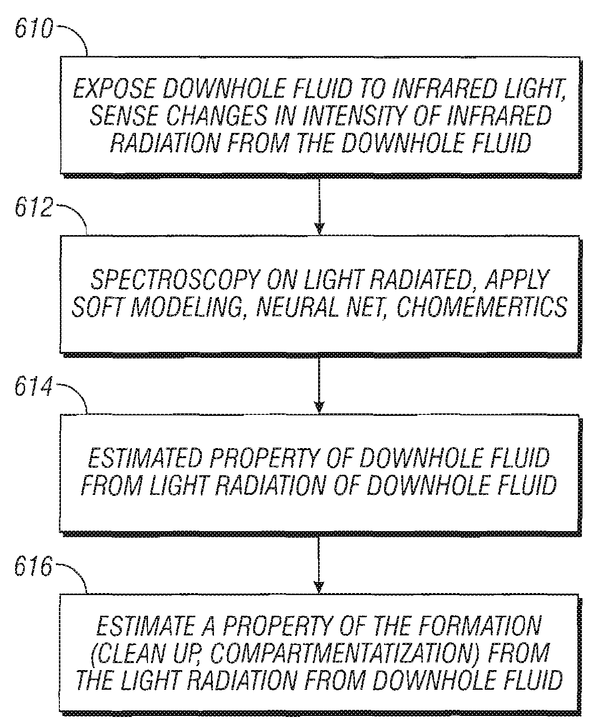
The present invention provides a method and apparatus for estimating properties of a fluid downhole by exposing the fluid to modulated light and sensing changes in intensity of the light. The invention uses infrared light to perform spectroscopic analysis of the fluid by interposing both the fluid and a detector between a light source and an object at different temperatures. The invention can estimate the presence of gases and parts per million of H2S in the fluid or gas. The invention also uses a soft modeling technique to estimate physical and chemical characteristics of the fluid or gas, such as density and viscosity. The invention can also estimate formation cleanup and the percentage of filtrate contamination in the fluid.

Problems solved by technology

It has not been performed downhole primarily because of the difficulty of performing MIR spectroscopy in the downhole environment.
The tool itself is very hot so it is continually emitting background MIR radiation, which could interfere with any readings taken by typical photodetectors.
Another challenging part of light detection in a downhole tool (such as a downhole spectrometer) is the effect of the high downhole temperatures (up to 200 C) on typical photodetectors.
Unfortunately, the smaller the bandgap, the more likely it is that, at elevated temperatures, some electrons will have enough thermal energy to reach the conduction band even when no light is being absorbed by the detector.
Exposure to light creates additional conduction electrons and holes, which cause the detector's resistance to drop.

Method used


Image

  • Method and apparatus for analyzing a downhole fluid using a thermal detector
  • Method and apparatus for analyzing a downhole fluid using a thermal detector
  • Method and apparatus for analyzing a downhole fluid using a thermal detector

Examples


Embodiment Construction

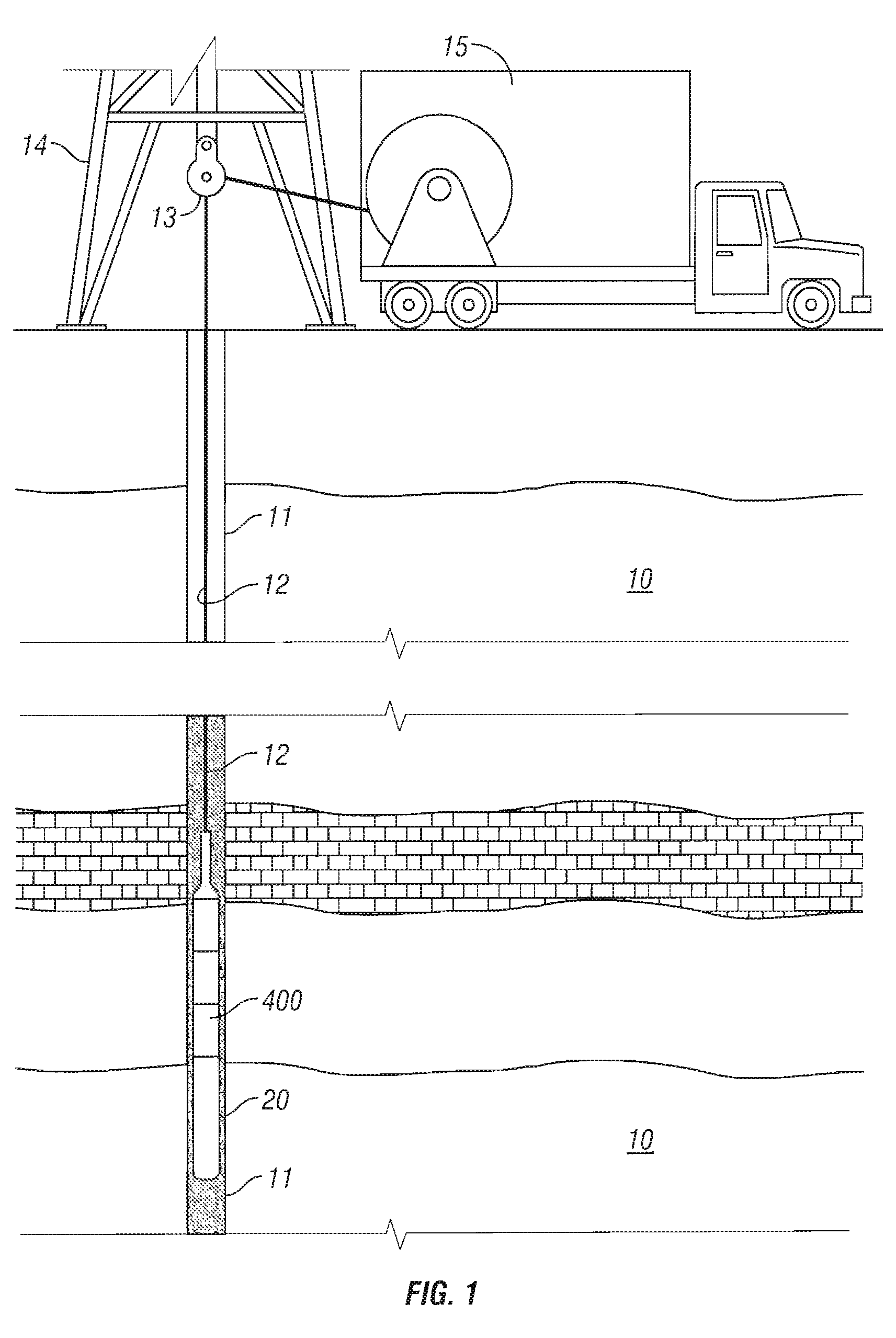
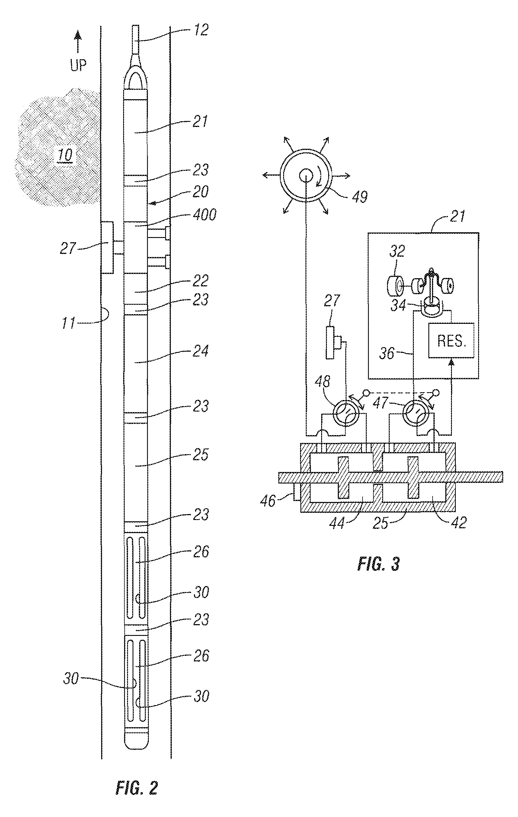
[0034]The present invention provides in one embodiment, a downhole infrared spectrometer using a detector such as a pyroelectric detector to enable spectral measurements from which estimates of the physical and chemical properties of a downhole fluid are made. The pyroelectric detector is provided in one embodiment to measure mid-infrared light downhole. Unlike photodiodes, pyroelectric detectors are based on a different principle so that the pyroelectric detectors do not have a shunt resistance problem at high temperatures downhole. Pyroelectric detectors are commonly used in the infrared motion detectors that automatically open the doors to a grocery store as a person approaches. Changes in the amount of light striking a pyroelectric detector cause miniscule, transitory changes in the detector temperature that generate a transient signal. This signal is not affected by the temperatures of the surroundings or by the detector's own temperature, provided that the detector temperature...


PUM


Abstract

The present invention provides a method and apparatus for estimating a property of a fluid downhole by exposing the fluid to modulated light downhole and sensing changes in intensity of infrared radiation from the downhole fluid to estimate the property of the downhole fluid. The present invention senses changes in intensity of light by converting the changes to transient changes in temperature of a detector, such as a pyroelectric detector. The present invention performs spectroscopic analysis of fluids by optically filtering the light allowed to impinge on a pyroelectric detector, converting the changes in temperature of the pyroelectric detector to a signal and converting the signal to estimate the property of the downhole fluid. The light source is modulated by mechanically chopping the beam or by electrically pulsing the light source or by steering the beam between different path lengths of sample or between a reference cell (filled with a reference fluid or empty) and a sample-filled cell.

Description

BACKGROUND OF THE INVENTION[0001]1. Field of the Invention[0002]The present invention relates generally to the field of downhole sampling and in particular to the downhole analysis of fluids and gases containing hydrocarbons using electromagnetic radiation (light) including Mid Infrared (MIR) light, Near Infrared (NIR) light and a temperature sensitive detector, such as a pyroelectric detector for measurement and estimation of properties of fluid and gas samples and properties of the reservoir from which a fluid or gas is taken, prior to, during, or after capture of the fluid or gas in a sample chamber.[0003]2. Summary of the Related Art[0004]In wellbore exploration, drilling mud such as oil-based mud and synthetic-based mud types are used. The filtrates from these mud types generally invade the formation through the borehole wall to an extent, meaning that these filtrates must be removed, as much as they can be removed, from the formation by pumping in order to access the formation...

Claims


Application Information

Patent Timeline
Patent Type & Authority Patents(United States)
IPC IPC(8): G01V5/08
CPCG01J3/02G01J3/0218G01J3/26G01J3/42G01N21/3577G01N21/8507G01N21/552G01N2201/0691G01N2201/129G01N21/3504
Inventor DIFOGGIO, ROCCOBERGREN, PAUL
Owner BAKER HUGHES INC
Learn More