Power conversion device and vehicle equipped therewith

a technology of power conversion device and power supply, which is applied in the direction of dc-ac conversion without reversal, motor/generator/converter stopper, dynamo-electric converter control, etc., can solve the problems that the matrix converter cannot use a plurality of power supplies together, neither select and charge, etc., and achieves the effect of small size and free movemen

Inactive Publication Date: 2008-09-09
TOYOTA JIDOSHA KK +1
View PDF13 Cites 15 Cited by
  • Summary
  • Abstract
  • Description
  • Claims
  • Application Information

AI Technical Summary

Benefits of technology

[0026]Preferably the control device reduces the rotation rate of the 3-phase alternating current rotary electric machine to reduce the maximum electromotive voltage to be lower than the inter-terminal voltage.
[0050]Furthermore the present invention provides a vehicle including m dc power supplies, an n-phase ac rotary electric machine, and the above described power conversion device converting power between the m dc power supplies and the n-phase ac rotary electric machine. Therefore the m dc power supplies and the n-phase ac rotary electric machine can communicate power variously in accordance with power flow patterns. Furthermore, a reactor, a capacitor and the like can be dispensed with, and reduced size and increased quietness, as required in particular for vehicles, can be achieved.

Problems solved by technology

The matrix converter disclosed herein, however, operates to perform power conversion between alternating currents between a main system outputting 3-phase ac power and a 3-phase asynchronous ac motor and in a fuel cell vehicle as described above cannot convert power between a plurality of dc power supplies and an ac motor.
Furthermore, this matrix converter can neither use a plurality of power supplies together to supply an ac motor with ac power nor select and charge a rechargeable power supply (or a secondary battery) when the ac motor regeneratively operates.

Method used


Image

  • Power conversion device and vehicle equipped therewith
  • Power conversion device and vehicle equipped therewith
  • Power conversion device and vehicle equipped therewith

Examples


first embodiment

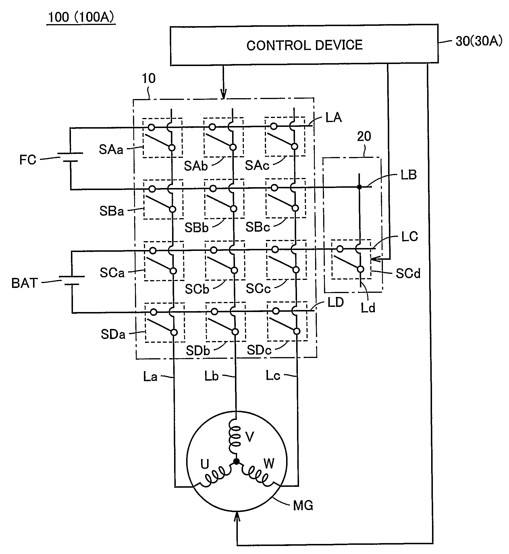
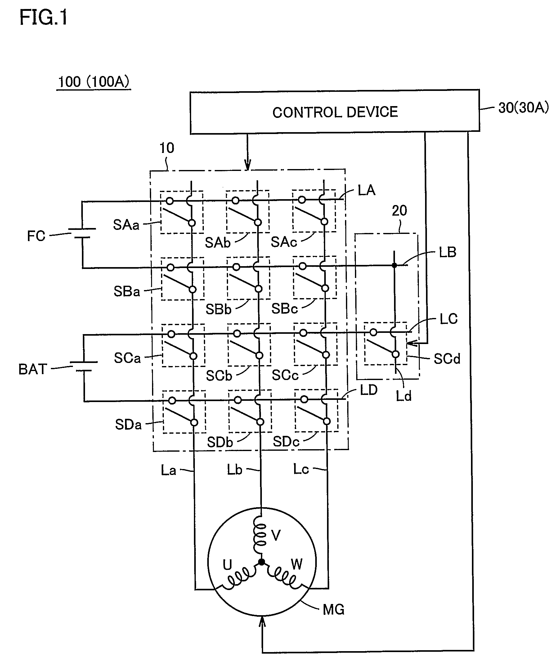
[0078]FIG. 1 is an electrical circuit diagram showing a configuration of a main portion of a power system in a fuel cell vehicle having the present power conversion device of the first embodiment mounted therein.

[0079]With reference to the figure, a fuel cell vehicle 100 includes a power conversion portion 10, a connection portion 20, a control device 30, a fuel cell FC, a battery BAT, and a motor generator MG.

[0080]Fuel cell FC is dc power generating cell obtaining electrical energy from energy generated by a chemical reaction caused for example between hydrogen or similar fuel and oxidizer. Fuel cell FC generates dc power which is in turn supplied to power conversion portion 10. Battery BAT is for example a secondary battery for example of nickel metal hydride or lithium ion or the like. Battery BAT supplies dc power to voltage conversion portion 10 and is charged with dc power received from power conversion portion 10.

[0081]Motor generator MG is a 3-phase ac synchronous motor gen...

second embodiment

in Exemplary Variation

[0171]In the second embodiment in the regenerative operation fuel cell FC is employed as a dc power supply and a d axis current is employed to control a magnetic field to weaken it. In the second embodiment in an exemplary variation when the d axis current is employed to control a magnetic field to weaken it connection portion 20 connects fuel cell FC and battery BAT in series to contemplate high voltage of a power supply in the d axis current control. This allows the d axis current control, i.e., controlling a magnetic field to weaken it, to be highly responsive.

[0172]FIG. 18 is a flow chart for control exerted for a regeneration operation in the second embodiment in the exemplary variation.

[0173]With reference to the figure, this flow corresponds to that for the regeneration operation in the second embodiment shown in FIG. 17 plus steps S15 and S35.

[0174]If at step S10 control device 30A determine that voltage max (Vmg) is equal to or larger than voltage Vbat...

third embodiment

in Fourth Exemplary Variation

[0208]FIG. 25 is an electrical circuit diagram showing an arrangement of the present power conversion device of the third embodiment in a fourth exemplary variation. With reference to the figure, a power conversion device 200D correspond to the FIG. 19 power conversion device 200 having connection portion 25 replaced with a connection portion 25D corresponding to the FIG. 23 connection portion 25C minus switches SCd, SEd, SEf.

[0209]More specifically the third embodiment and its first to third exemplary variations tolerate reverse connection of batteries in connection portions 25-25C, respectively. The third embodiment in the fourth exemplary variation further eliminates switches SCd, SEd, SEf reversely connecting batteries BAT1-BAT3 by providing power conversion portion 15 with a function reversely connecting a battery to compulsorily, directly charge one battery from another battery, and causing connection portion 25 to serve to forward-connect a plural...


PUM


Abstract

A power conversion portion (10) and a connection portion (20) converting power between a fuel cell (FC) and a battery (BAT) corresponding to dc power supply and a motor generator (MG) corresponding to an ac machine, are configured of a matrix converter. For a power flow pattern requiring that the dc power supply provide high voltage, a switch (SCd) in the connection portion (20) operates in response to a control signal received from a control device (30) to electrically connect a power supply line (LC) to a power supply line (Ld) to connect the fuel cell (FC) and the battery (BAT) in series.

Description

TECHNICAL FIELD[0001]The present invention relates to power conversion devices and vehicles equipped therewith and particularly to power conversion devices employing a matrix converter and vehicles equipped therewith.BACKGROUND ART[0002]In recent years as energy conservation and environmental issues are increasingly discussed, electric vehicles are increasingly noted. Electric vehicles are vehicles having as a source of power a direct current (dc) power supply, an inverter, and a motor driven by the inverter.[0003]One such conventionally known electric vehicle is a fuel cell vehicle employing a fuel cell for a dc power supply. Generally a fuel cell vehicle is equipped with a secondary battery for recovering energy regenerated by a motor in a regeneration mode, and uses the regenerated power to charge the secondary battery and uses the fuel cell and the secondary battery together to supply power of high voltage to the motor.[0004]More specifically in such fuel cell vehicle the motor ...

Claims


Application Information

Patent Timeline
Patent Type & Authority Patents(United States)
IPC IPC(8): H02M7/797B60L11/18H02M7/48
CPCH02M7/797H02M7/487
Inventor OYOBE, HICHIROSAIISHIKAWA, TETSUHIROYANO, TSUYOSHIKIMATA, MASAHIROMAJUMDAR, GOURABYU, YOSHIHARU
Owner TOYOTA JIDOSHA KK
Why Eureka
Try Eureka