Method and apparatus for transmitting energy via a laser beam

Inactive Publication Date: 2008-09-09
ASTRIUM GMBH
View PDF15 Cites 49 Cited by
  • Summary
  • Abstract
  • Description
  • Claims
  • Application Information

AI Technical Summary

Benefits of technology

[0008]According to another advantageous further embodiment of the invention, the position of the laser beam is modulated, whereby the relative position of the laser beam impinging on the radiation receiver, and therewith also the motion of the receiver unit relative to the transmitter unit, can be analyzed or evaluated on the basis of the modulation information returned in the reflected light. The emitted laser beam is then appropriately moved or directed by the transmitter unit so as to follow or track the receiver unit on the basis of this information. The regulation according to the invention in this manner, which is based on measuring and evaluating or analyzing the intensity of the reflected radiation, thereby makes it possible for the emitted laser beam to follow or track the receiver unit during the movement of the receiver unit both in the horizontal direction as well as the vertical direction.

Problems solved by technology

As mentioned, the known methods and apparatuses are practically exclusively used for the transmission of energy over short distances and only for small energy quantities, because it has previously not been practically possible to transmit large energy quantities over large distances, due to shortcomings of the known energy transmission methods and apparatuses.

Method used


Image

  • Method and apparatus for transmitting energy via a laser beam
  • Method and apparatus for transmitting energy via a laser beam
  • Method and apparatus for transmitting energy via a laser beam

Examples


Embodiment Construction

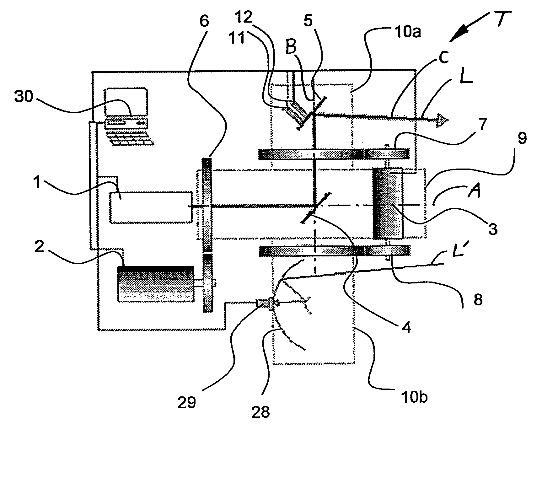
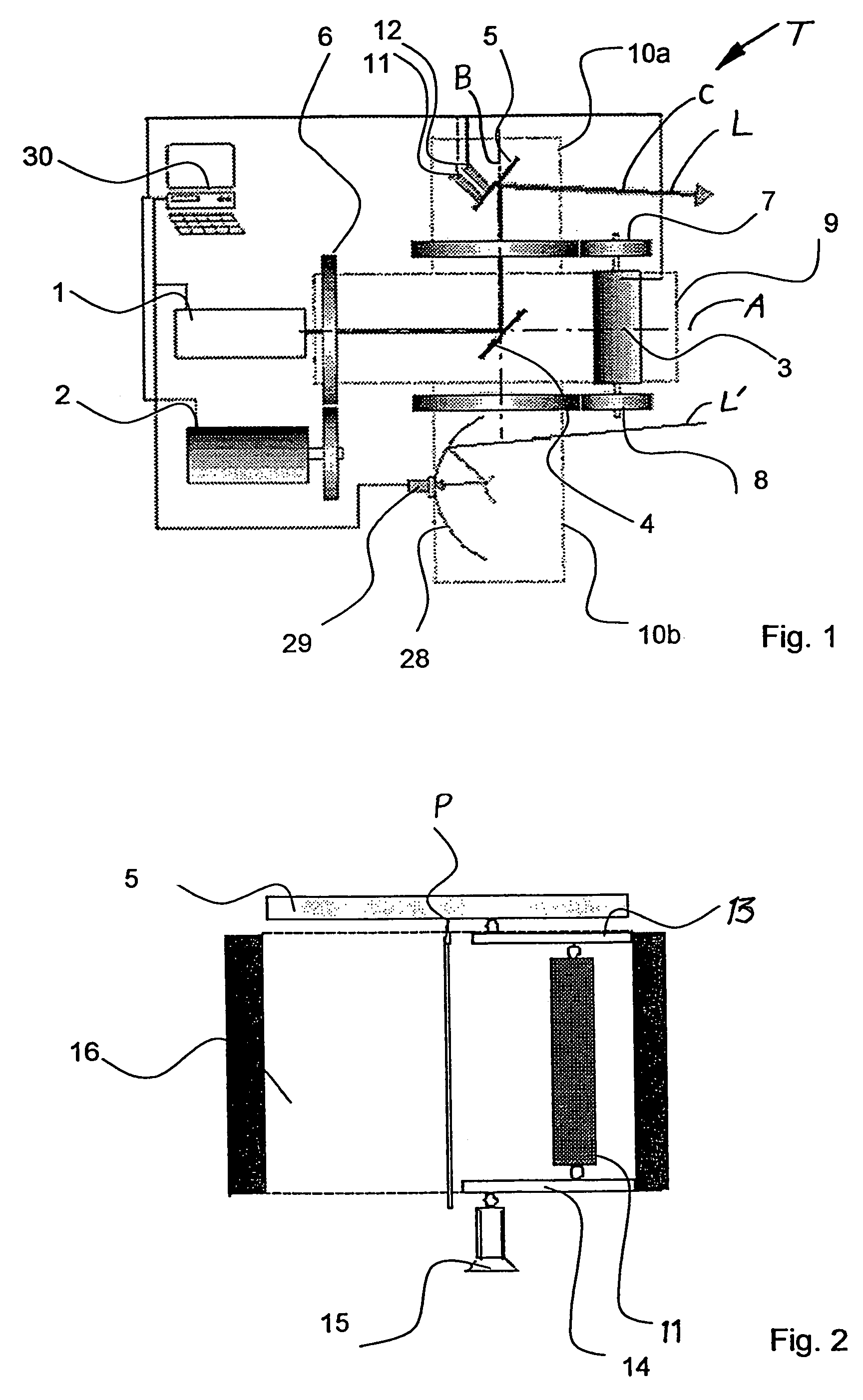
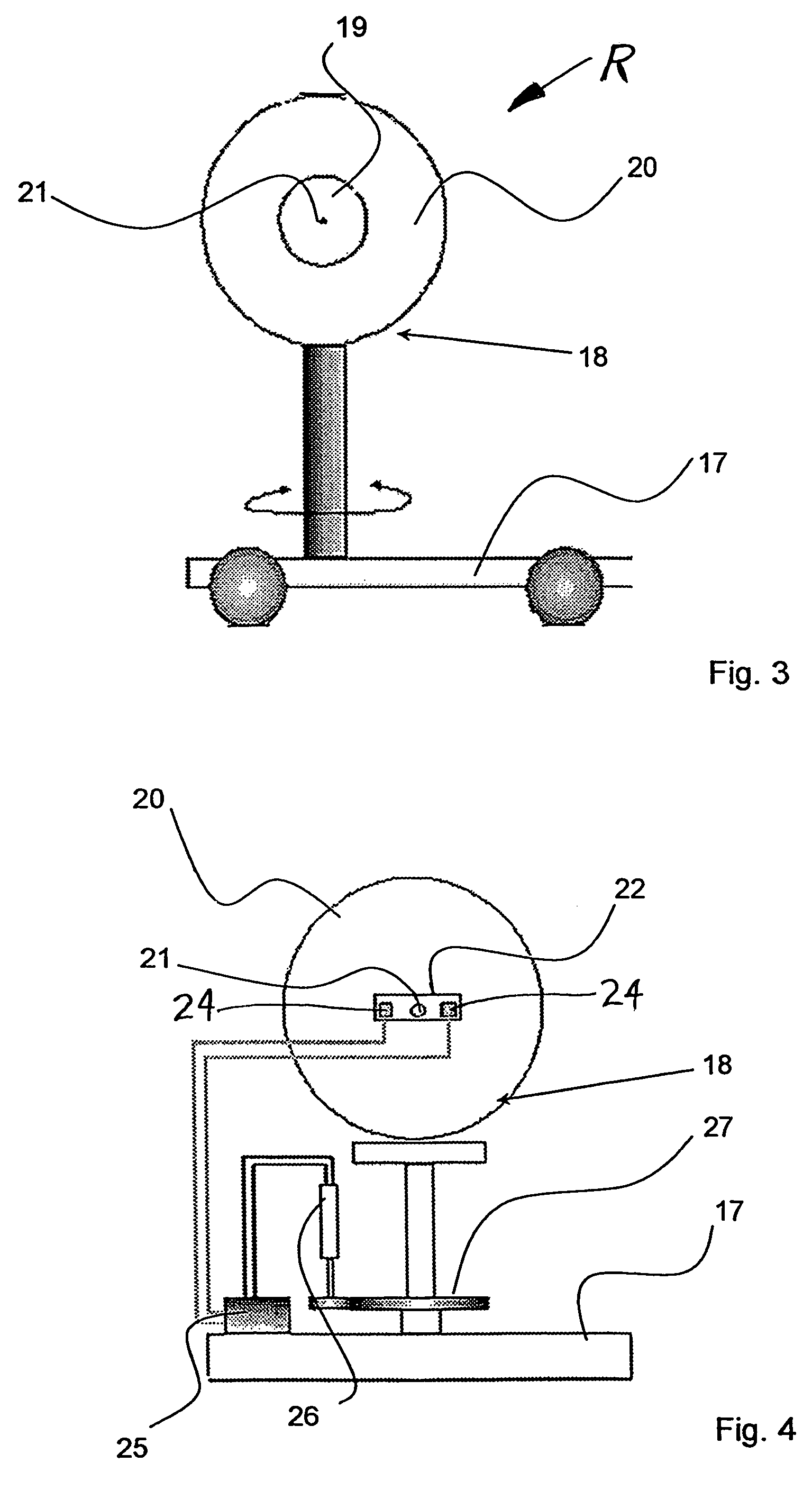
[0021]The inventive apparatus or system for transmitting energy includes a transmitter unit T (see FIGS. 1 and 2) and a receiver unit (R) (see FIGS. 3 to 5), which are arranged remotely and are autonomous from one another, and which have no direct mechanical and / or electrical connection therebetween for transmitting energy therebetween. The transmitter unit T generates and emits a laser beam L that is transmitted over a substantial distance to the receiver unit R, which receives the laser beam L and extracts its required operating energy supply from the laser beam L. For example, the receiver unit R includes a laser beam radiation receiver arrangement incorporating one or more photovoltaic or “solar” cells, which receive the incident laser beam L and convert the received beam energy into electrical energy, which is then used to satisfy at least a portion, or preferably all, of the on-board operating energy requirements of the receiver unit R. The receiver unit R may be embodied to c...


PUM

PropertyMeasurementUnit
wavelengthaaaaaaaaaa
angleaaaaaaaaaa
rotation anglesaaaaaaaaaa

Abstract

To transmit energy without direct mechanical or electrical contact, a transmitter unit emits a laser beam onto a radiation receiver of a receiver unit including a photovoltaic cell arrangement surrounded by a ring-shaped reflector. A portion of the laser beam is reflected from the reflector back to the transmitter unit, where the received reflected signal is evaluated to determine the position of the laser beam impinging on the radiation receiver. The transmitter unit deflects the laser beam as necessary to impinge directly on the photovoltaic cell arrangement and track any relative motion of the receiver unit. The receiver unit orients the radiation receiver to optimize the energy reception. The position of the laser beam is modulated and the resulting variation of the reflected signal is evaluated to determine therefrom the position of the laser beam on the radiation receiver.

Description

PRIORITY CLAIM[0001]This application is based on and claims the priority under 35 U.S.C. §119 of German Patent Application 10 2004 008 681.8, filed on Feb. 21, 2004, the entire disclosure of which is incorporated herein by reference.FIELD OF THE INVENTION[0002]The invention relates to a method and an apparatus for transmitting energy from a transmitter unit to a receiver unit by means of coherent electromagnetic radiation.BACKGROUND INFORMATION[0003]Methods and apparatuses of the above mentioned general type are conventionally known for transmitting relatively small energy quantities over relatively short distances without a direct mechanical and / or electrical contact between a transmitter unit and a receiver unit. The receiver unit can then make use of the received energy for its own autonomous energy supply needs. As mentioned, the known methods and apparatuses are practically exclusively used for the transmission of energy over short distances and only for small energy quantities...

Claims


Application Information

Patent Timeline
Patent Type & Authority Patents(United States)
IPC IPC(8): G01B11/00G01C3/08G01N21/86G02B26/08B64G1/42H02J17/00H04B10/118H04B10/80
CPCB64G1/428H04B10/806H04B10/118H02J17/00H02J50/30H02J50/90
Inventor STEINSIEK, FRANKWEBER, KARL-HEINZFOTH, WOLF-PETERFOTH, HANS-JOCHENSCHAEFER, CHRISTIAN
Owner ASTRIUM GMBH
Why Eureka
Try Eureka