
Air shroud installed on a circuit board

a technology of air shroud and circuit board, which is applied in the direction of electrical apparatus casing/cabinet/drawer, cooling/ventilation/heating modification, instruments, etc., can solve the problems of increasing the cost of fans, unable to lead air flow in a higher speed to aim at an area or electronic component requiring more heat dissipation, etc., to achieve fast speed and dissipate heat from a specific electronic componen

Active Publication Date: 2008-09-09
SUPER MICRO COMP
View PDF11 Cites 10 Cited by
  • Summary
  • Abstract
  • Description
  • Claims
  • Application Information

AI Technical Summary

Benefits of technology

The present invention provides an air shroud that can quickly suck air in a local space on a circuit board and expel it in a specific direction. This allows the air to flow quickly and efficiently, either dissipating heat from a specific electronic component or being expelled into another space area. The technical effect of this invention is to provide a more efficient and effective air flow on circuit boards.

Problems solved by technology

However, as both a space along a suction direction and a space along an expelling direction of a fan are extremely large, it is unable to lead air flow in a higher speed to aim at an area or electronic component requiring more heat dissipation for dissipating the heat.
In other words, if it is required to dissipate heat for more areas or electronic components, more fans need to be added to solve this kind of problem, which will increase a cost of fan, and will also consider that whether there is sufficient space inside the computer casing for installing more fans.

Method used


Image

  • Air shroud installed on a circuit board
  • Air shroud installed on a circuit board
  • Air shroud installed on a circuit board

Examples


Embodiment Construction

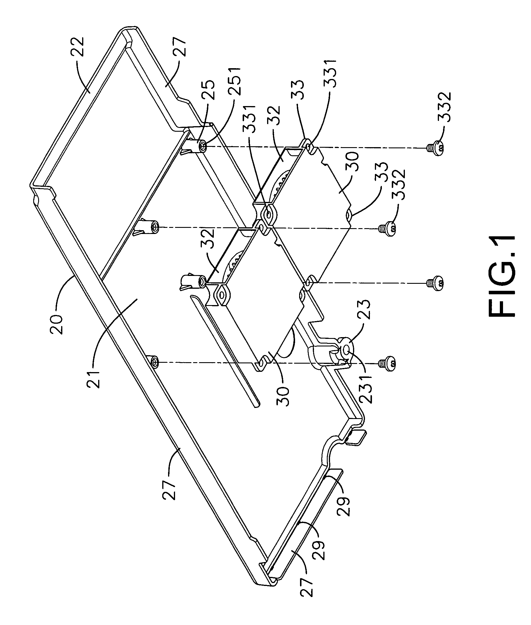
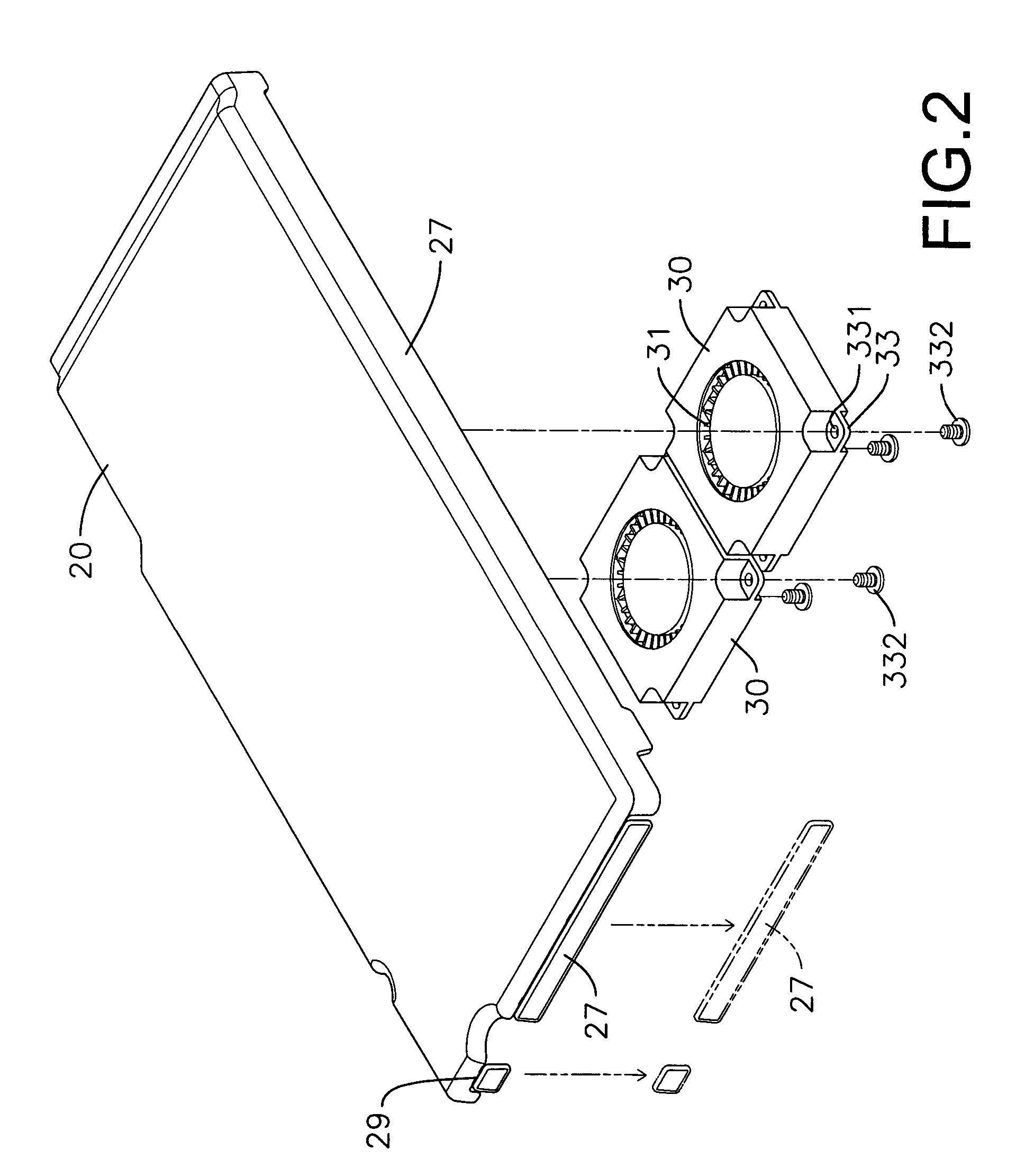
[0013]Referring to FIGS. 1 to 3, the present invention is to provide a air shroud installed on a circuit board, including an outer housing 20, which is installed on a circuit board 10, an inner surface of which is connected with at least more than one fan 30, and a side of which is provided with an air exit 22; the fans 30 which are provided with air entrances 31 and air exits 32 (as shown in FIG. 1 and FIG. 2), wherein the air exits 32 are corresponding to the air exit 22 of outer housing 22. Air sucked in by the air entrances 31 of fans 30 is expelled out of the air exit 22 of outer housing 20 to be exported, through the air exits 32.

[0014]Referring to FIGS. 1 to 3, the outer housing 20 is a rectangular casing which is provided with at least one connection seat 23 having a through-hole 231, and is screwed onto the circuit board 10 through a bolt 232. The outer housing 20 is installed on the circuit board 10, and a gap 18 is formed between the outer housing 20 and the circuit board...


PUM


Abstract

A air shroud installed on a circuit board is composed of a circuit board which is installed with an outer housing, an inner surface of which is connected with at least more than one fan, and a side of which is provided with an air exit. The fan is provided with an air entrance and an air exit, wherein the air exit is corresponding to the air exit of outer housing. Air sucked in by the air entrance of fan is expelled out of the air exit of outer housing to be exported, through the air exit of fan, such that the air can be led to another space area or be used to dissipate heat from a specific electronic component.

Description

BACKGROUND OF THE INVENTION[0001]a) Field of the Invention[0002]The present invention relates to a air shroud installed on a circuit board, and more particularly to a air shroud which can suck and accumulate air in a space on a circuit board and expel it along a specific direction, so as to provide the expelled air flow to a specific space or to a specific electronic component for dissipating heat.[0003]b) Description of the Prior Art[0004]It is well known that a conventional computer motherboard, especially a motherboard of an industrial computer, is welded with a large quantity of chips, central processing units, and memories, which can be distributed among different compartments and positions. However, as both a space along a suction direction and a space along an expelling direction of a fan are extremely large, it is unable to lead air flow in a higher speed to aim at an area or electronic component requiring more heat dissipation for dissipating the heat. In other words, if it...

Claims


Application Information

Patent Timeline
Patent Type & Authority Patents(United States)
IPC IPC(8): H05K7/20H05K5/00
CPCG06F1/20
Inventor CHEN, RICHARD
Owner SUPER MICRO COMP
Learn More