
Optical member and optical communication module with easy height adjustment

a technology of optical communication module and height adjustment, which is applied in the field of optical members, can solve the problems of time-consuming, time-consuming, and inability to adjust the position of such a configuration, and achieve the effects of convenient adjustment, improved accuracy, and broad coverag

Active Publication Date: 2008-09-09
ALPS ALPINE CO LTD
View PDF9 Cites 5 Cited by
  • Summary
  • Abstract
  • Description
  • Claims
  • Application Information

AI Technical Summary

Benefits of technology

The present invention provides an optical member that can be easily adjusted in the height direction. The optical member includes a lens that is positioned at one end of a rectangular columnar body made of optical material. The lens is positioned in a way that its center position is offset from the end face center position of the body. The optical member also has a beveled portion at a corner between adjacent side faces, and a square sectional shape. This design allows for precise and easy adjustment of the lens position in the height direction, and ensures a wide coverage of the lens. The optical member can be easily determined in terms of its height position pattern due to the beveled portion. The symmetrical shape of the body also makes it easy to form the optical member with accuracy. The optical communication module using this optical member has the advantage of easy adjustment of the optical member position in the height direction.

Problems solved by technology

In a configuration in which a lens is disposed on a silicon substrate, the lens has to be fixed at an accurate position relative to the silicon substrate; the position adjustment for such a configuration has been a difficult task.
Another problem with the configuration has been that the use of a silicon substrate inhibits miniaturization of the optical communication module.
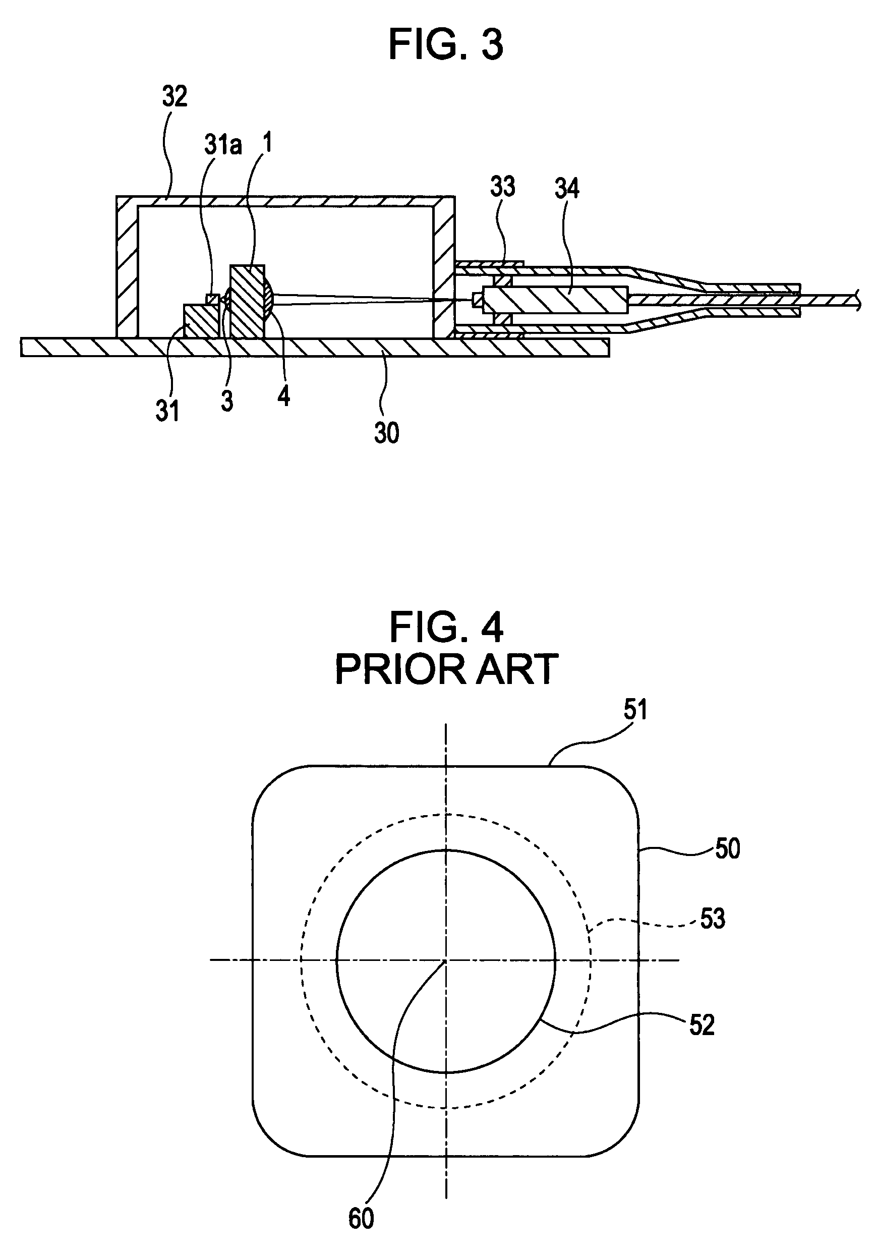
The height of the rectangular columnar body 51 is adjusted by shaving the side face thereof or by disposing a height adjustment spacer, which is a time-consuming job and becomes a factor of cost up.

Method used


Image

  • Optical member and optical communication module with easy height adjustment
  • Optical member and optical communication module with easy height adjustment
  • Optical member and optical communication module with easy height adjustment

Examples


Embodiment Construction

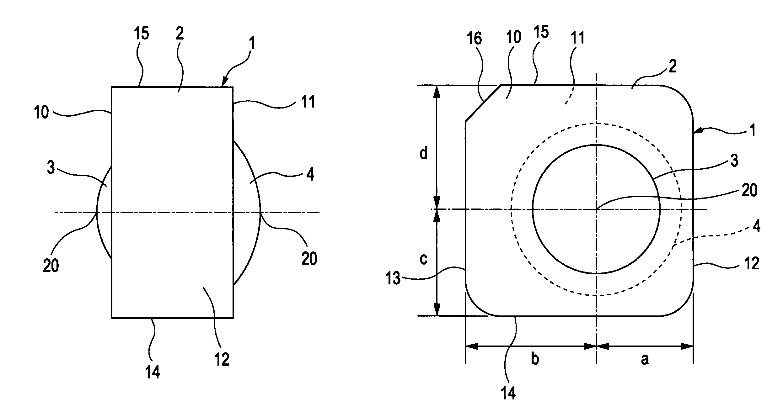
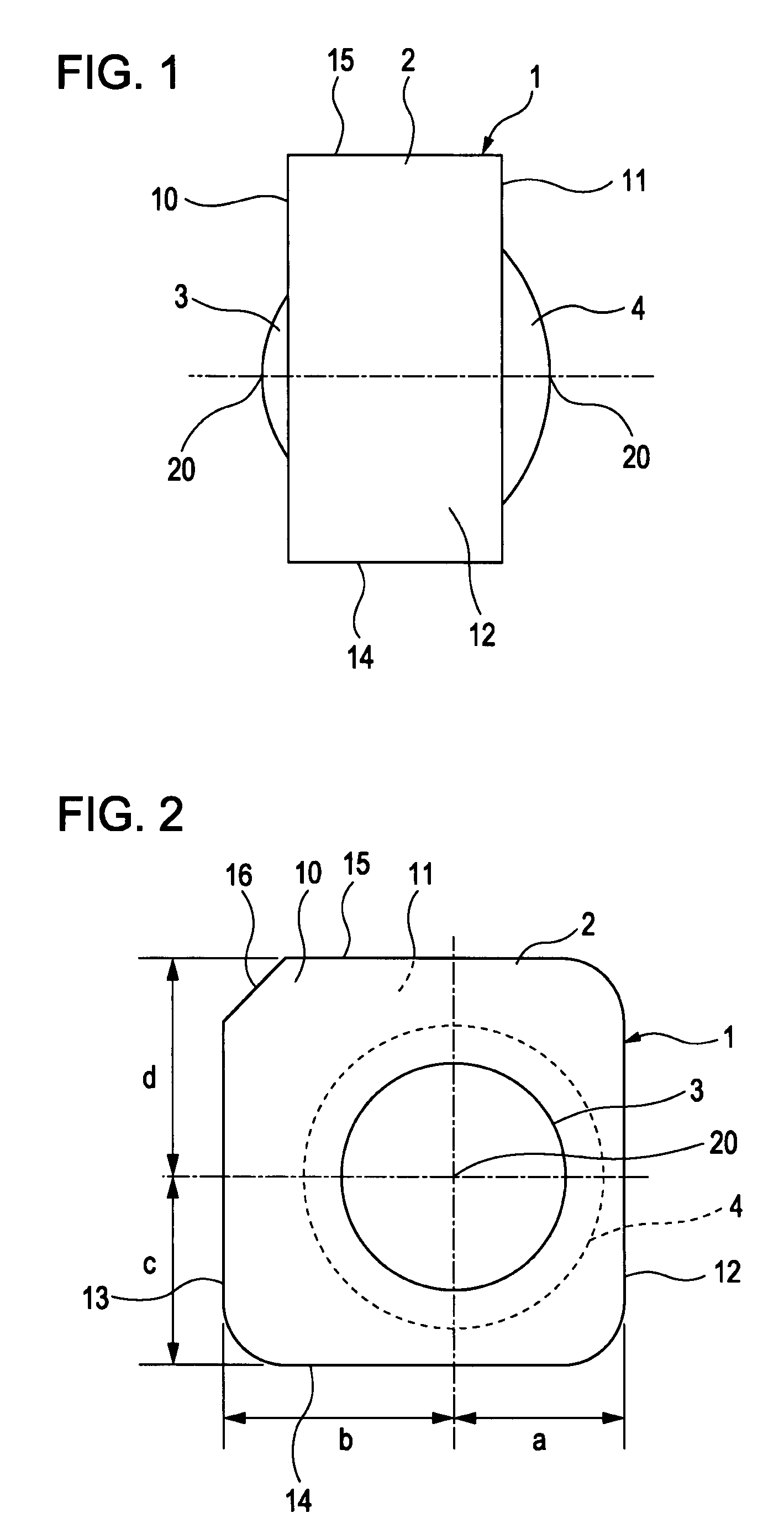
[0024]An embodiment of the present invention will be described with reference to the figures. A side view and a front view of an optical member in this embodiment are respectively shown in FIGS. 1 and 2. As shown in each figure, an optical member 1 in this embodiment consists of a body 2 formed substantially in a rectangular column shape and convex shaped lenses 3, 4 respectively formed on the end faces 10, 11 of the body 2.

[0025]As shown in FIG. 1, the first lens 3 is formed on one end face 10 of the body 2, and the second lens 4 is formed on the other end face 11 of the body 2. The first and second lenses 3, 4 are disposed so that their center positions 20 are collinear at respective end faces 10, 11 of the body 2. The first lens 3 is formed to be smaller in diameter than the second lens 4; thereby, diverged light incident to the first lens 3 is emitted from the second lens 4 as converged light.

[0026]Because of being formed substantially in a rectangular column shape, the body 2 h...


PUM


Abstract

An optical member includes a body made of an optical material and formed in a square sectional shape, and a lens disposed on at least one end face of the body so that the distances from the lens center to each of the side faces of the body are all different. The optical member is incorporated in an optical communication module as a component for coupling light from a light-emitting device to the end face of an optical fiber.

Description

BACKGROUND OF THE INVENTION[0001]1. Field of the Invention[0002]The present invention relates to an optical member having lenses and an optical communication module using the same, and more specifically to an optical member usable for plane mounting and an optical communication module using the same.[0003]2. Description of the Related Art[0004]In an optical communication module, a lens is used for coupling light from a light-emitting device to an optical fiber. The lens, normally having a circular shape, is usually disposed at a V-shaped groove formed on a silicon substrate on which the light-emitting device is provided, since the lens should be positioned so as to match the level of the light-emitting device. An example of such an optical communication module is presented in Japanese Unexamined Patent Application Publication No. 2000-12183.[0005]In a configuration in which a lens is disposed on a silicon substrate, the lens has to be fixed at an accurate position relative to the si...

Claims


Application Information

Patent Timeline
Patent Type & Authority Patents(United States)
IPC IPC(8): G02B6/32
CPCG03B13/20
Inventor HATAKEYAMA, SHIGERUKONNO, KAZUHIRO
Owner ALPS ALPINE CO LTD
Learn More