Torque resistant fastening element

a technology of fastening elements and torque resistance, which is applied in the direction of threaded fasteners, screwed fasteners, manufacturing tools, etc., can solve the problems of insufficient torque resistance, insufficient torque resistance, and metal may not be fully deformed into the pockets, so as to improve torque resistance, provide torque resistance, and improve torque resistance

Active Publication Date: 2008-09-16
PENN AUTOMOTIVE INC
View PDF12 Cites 24 Cited by
  • Summary
  • Abstract
  • Description
  • Claims
  • Application Information

AI Technical Summary

Benefits of technology

[0010]The outer surface of the radial flange portion of the self-attaching fastener element of this invention includes a plurality of circumferentially spaced radial projections each including an outer surface having a diameter greater than the tubular barrel portion and the panel is incrementally deformed radially inwardly into the recesses between the radial projections by the die button during installation and thus provide torque resistance. In a preferred embodiment of the self-attaching fastener element of this invention, the outer surface of the radial flange portion between the circumferentially spaced radial projections has a greater circumferential width than a circumferential width of the outer surface of the radial projections providing further improved torque resistance as the panel is deformed between the circumferentially spaced radial projections. In a more preferred embodiment of the self-attaching fastener element of this invention, the circumferential width of the radial flange portion between the circumferentially spaced radial projections is at least twice the circumferential width of the outer surface of the radial projection, providing further improved torque resistance. Further, in a preferred embodiment of the self-attaching fastener element of this invention, the circumferentially spaced radial projections each include opposed planar generally radial side surfaces extending from the outer surface of the radial flange portion to the outer surface of the circumferentially spaced radial projections, such that the side walls are generally perpendicular to a circumferential rotation about the longitudinal axis of the tubular barrel portion and the radial flange portion, providing optimal torque resistance as torque is applied to the fastener element following installation. That is, the planar generally radial side surfaces or faces of the circumferentially spaced radial projections is generally perpendicular to the torsional force applied to the self-attaching fastener element, providing optimal torque resistance. However, the circumferentially spaced radial projections may still sheer under extreme torsional load and thus in a preferred embodiment of the self-attaching fastener element of this invention, the circumferential width of the outer surface of the radial projections is greater than the radial length of the radial projections and in a more preferred embodiment, the circumferential width of the outer surface of the radial projections is at least twice the radial length, providing improved strength for the radial projections under torsional load.

Problems solved by technology

There remains, however, several problems associated with the use of pockets in the flange as disclosed in U.S. Pat. No. 5,020,950, including wear of the die surfaces which form the pockets, such that the pockets are not always fully formed in the flange portion resulting in insufficient torque resistance.
Second, the self-attaching fastener and panel assembly is press sensitive.
That is, the panel metal may not be fully deformed into the pockets and thus the torque resistance will be inadequate.
Further, the pockets form stress risers in the panel which can become a source of failure of the fastener and panel assembly.
Finally, the use of pockets in the flange portion may provide insufficient torque resistance, particularly where extreme torque resistance is required.
Although the arcuate design of the radial flange portion disclosed in U.S. Pat. No. 5,868,535 increases the torque resistance and the arcuate configuration is beneficial to deforming the panel due to the smooth transition of its arcuate shape, the torque resistance provided by this self-attaching fastener is still insufficient for certain applications.
However, the configuration of the radial teeth disclosed in this patent will shear the panel under the torque load encountered in many applications.

Method used


Image

  • Torque resistant fastening element
  • Torque resistant fastening element
  • Torque resistant fastening element

Examples


Embodiment Construction

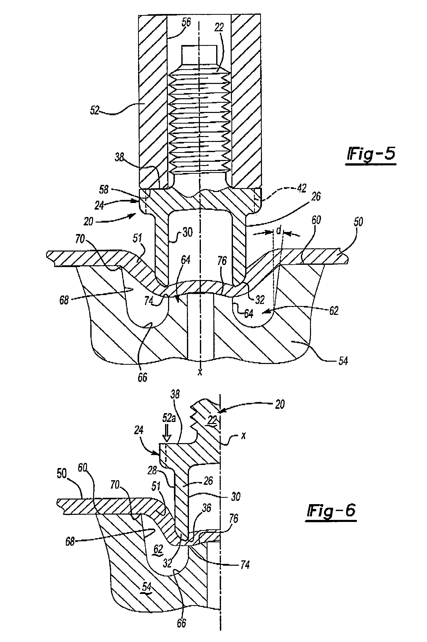
[0026]As set forth above, this invention relates to improved self-attaching fastener elements having significantly improved torque resistance. As will be understood by those skilled in this art, the drawings illustrate preferred embodiments of the self-attaching fastener element of this invention, but are not limiting except as set forth in the appended claims. Although the figures illustrate that the self-attaching fastener of this invention may be utilized as a self-piercing fastener element, the invention is not limited to self-piercing fasteners and the self-attaching fastener of this invention may also be utilized as a self-clinching fastener, wherein the opening through the panel is prepierced or preformed.

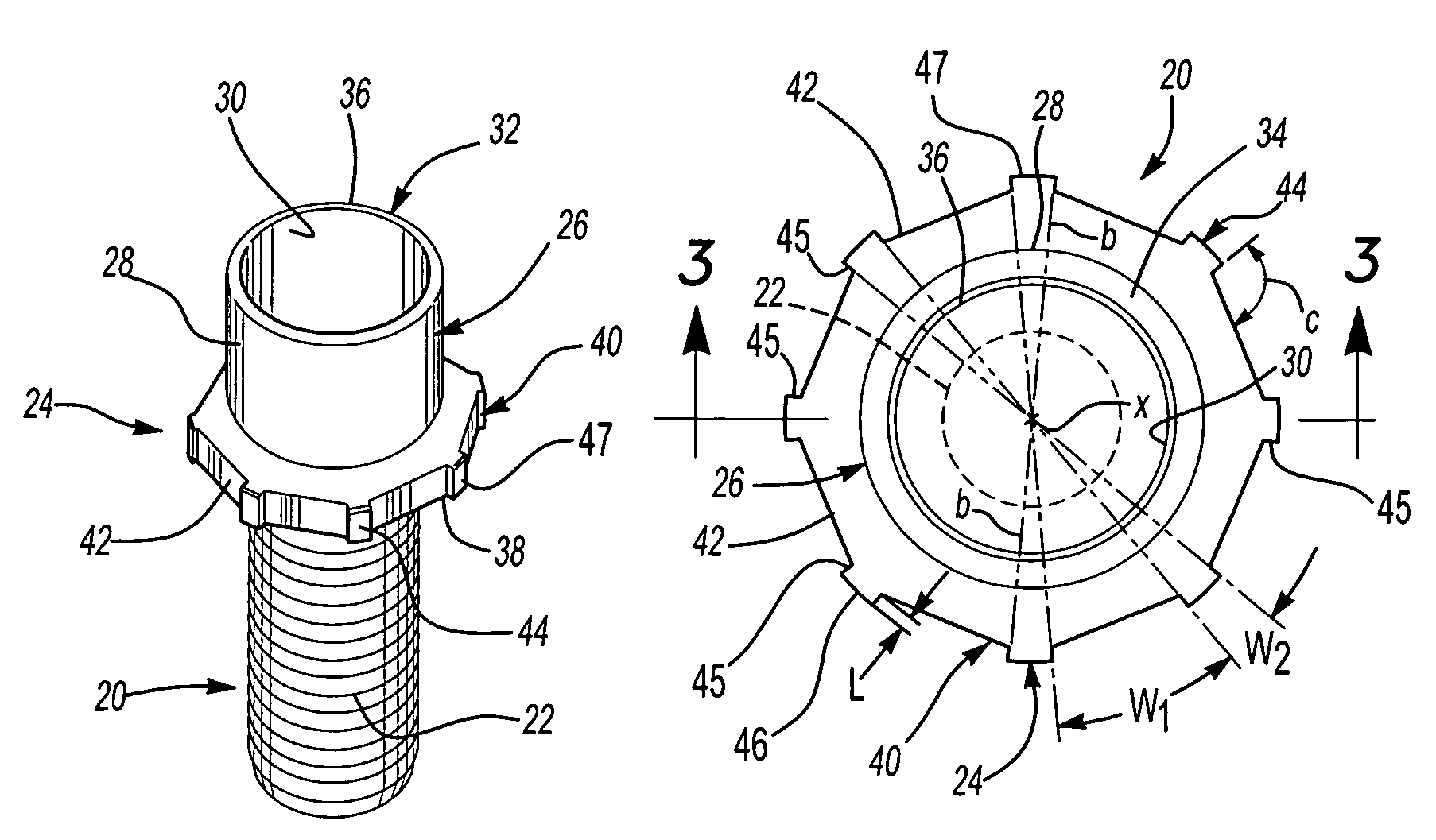
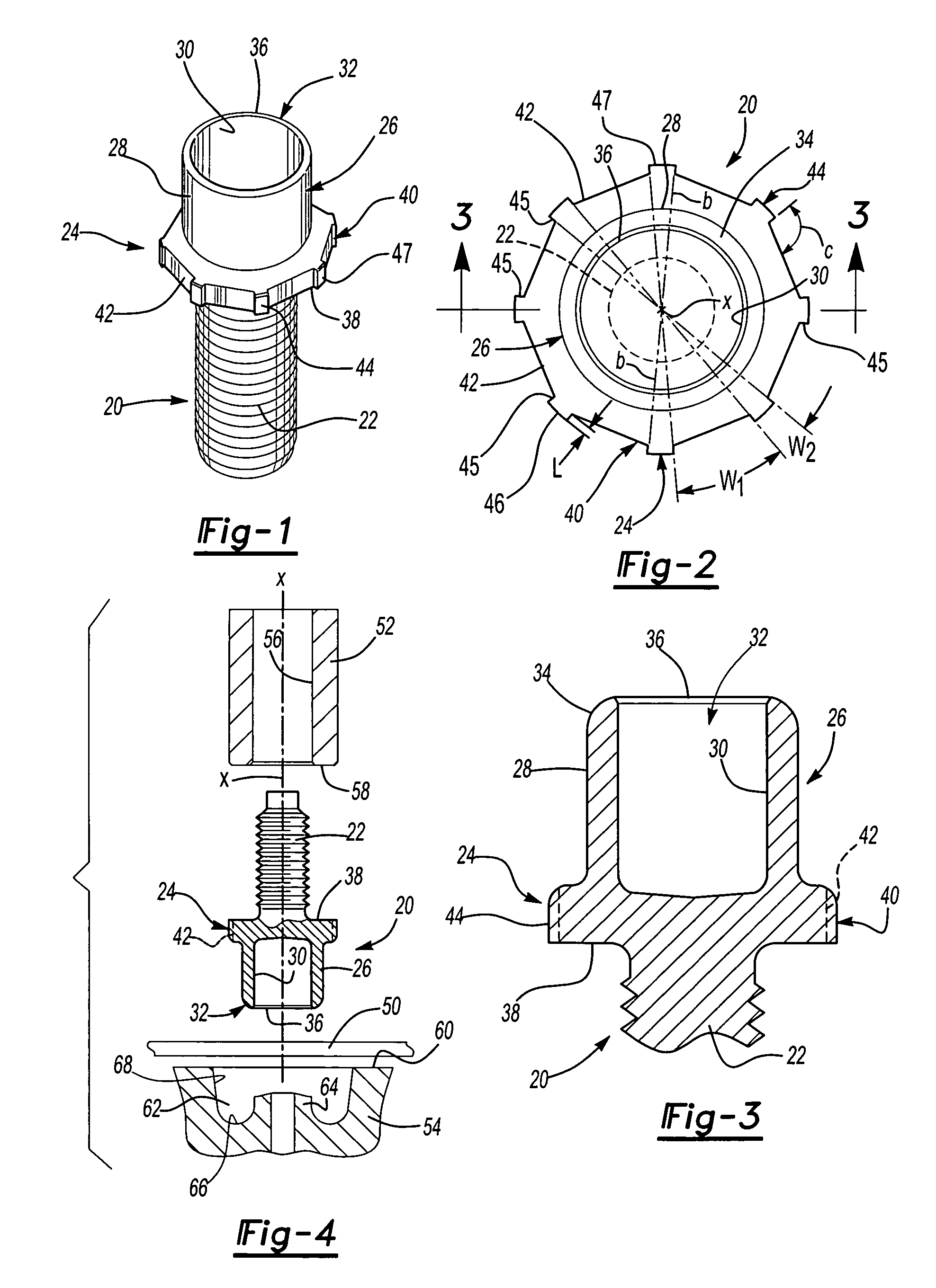
[0027]FIGS. 1 to 3 illustrate a first embodiment of the self-attaching fastener of this invention generally shown at 20 in the form of a male self-attaching fastener having a threaded shank portion 22, although the shank portion may also be unthreaded. In the embodiment of t...


PUM

PropertyMeasurementUnit
included angleaaaaaaaaaa
diameteraaaaaaaaaa
diameteraaaaaaaaaa

Abstract

A torque resistant self-attaching fastener having a tubular barrel portion and a radial flange portion including a plurality of circumferentially spaced radial projections each having opposed planar generally radial side faces with the outer surface of the radial flange between the radial projections having a greater circumferential width than a circumferential width of the radial projections and a radial length less than the circumferential width. The side faces may be aligned with a radius, the side faces may be parallel or the side faces of adjacent radial projections may be parallel.

Description

RELATED APPLICATIONS[0001]This application is a continuation-in-part application of U.S. Ser. No. 10 / 714,265 filed Nov. 14, 2003 now abandoned and Ser. No. 10 / 271,480 filed Oct. 16, 2002 now U.S. Pat. No. 7,179,034.FIELD OF THE INVENTION[0002]This invention relates to a fastener or fastening element having a tubular barrel portion and an integral radial flange portion opposite the free open end of the tubular barrel portion for attachment to a metal panel, wherein the tubular barrel portion is deformed to form a mechanical interlock with the panel. More specifically, this invention relates to a fastener element having a plurality of circumferentially spaced radial projections on the radial flange portion to improve the torque resistance of the fastener element following installation in a panel.BACKGROUND OF THE INVENTION[0003]Self-piercing and clinching fasteners, such as nuts, were developed by a predecessor in interest of the Applicant (Multifastener Corporation) more than 50 year...

Claims


Application Information

Patent Timeline
Patent Type & Authority Patents(United States)
IPC IPC(8): F16B37/04B23P19/06F16B33/00F16B37/06
CPCB23P19/062F16B37/068F16B37/062F16B33/002Y10T29/49837Y10T29/49835
Inventor LADOUCEUR, HAROLD A.
Owner PENN AUTOMOTIVE INC
Why Eureka
Try Eureka