Exhaust assembly

a technology of exhaust air and assembly, which is applied in the direction of liquid separation agent, filtering of dispersed particles, application, etc., can solve the problems of difficult housing of such filters in the cleaner, the risk of a small amount of dust passing through the separator and being carried to the fan and motor unit, and the physical bulk of the filter body. , to achieve the effect of reducing noise, reducing back pressure, and slowing down the exhaust airflow

Inactive Publication Date: 2008-09-16
DYSON TECH LTD
View PDF16 Cites 29 Cited by
  • Summary
  • Abstract
  • Description
  • Claims
  • Application Information

AI Technical Summary

Benefits of technology

[0007]The vanes help to more evenly distribute air across the full cross-section of the exhaust duct and thereby slow the exhaust airflow. This can help to reduce noise and can reduce the back pressure that a faster-flowing flow would otherwise cause. The arrangement is particularly beneficial in any exhaust assembly where the exhaust duct is mounted in such a way that exhaust air, in use, will not readily distribute itself across the exhaust duct.
[0008]Preferably there are at least two vanes positioned within the filter housing and the vanes are spaced from one another in a cross-section through the proximal end of the exhaust duct. An increased number of vanes helps to more evenly distribute the exhaust airflow.
[0009]Preferably the vanes are carried by a cover of the filter housing. Preferably the filter housing comprises apertures for allowing some of the exhaust airflow to vent to atmosphere without passing through the exhaust duct. This helps to reduce the flow of air which needs to pass along the exhaust duct.

Problems solved by technology

Whichever type of separator is employed, there is commonly a risk of a small amount of dust passing through the separator and being carried to the fan and motor unit, which is used to create the flow of air through the vacuum cleaner whilst it is in operation.
There is an increasing awareness among consumers of the problem of emissions, which can be particularly problematic for asthma sufferers.
Such filters are physically bulky and housing such filters in the cleaner is quite challenging.
However, an increased rate of airflow can cause the machine to be noisy in operation.
This has a detrimental effect on the overall rate of airflow through the machine in addition to adding both weight and cost to the machine.

Method used


Image

  • Exhaust assembly
  • Exhaust assembly
  • Exhaust assembly

Examples


Embodiment Construction

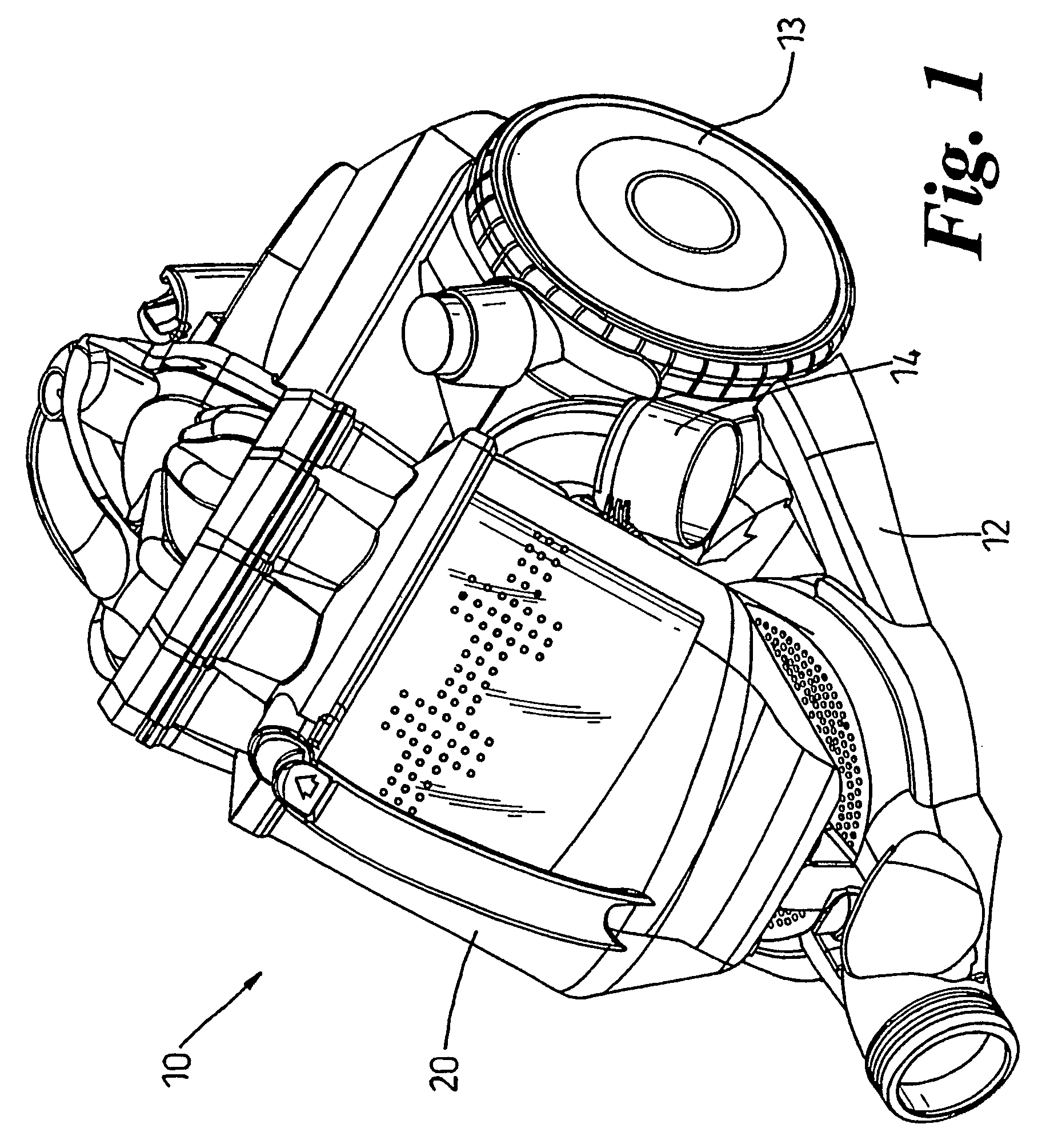
[0024]FIGS. 1 to 3 show an example of a vacuum cleaner 10 in which the invention is embodied. The vacuum cleaner 10 is a cylinder or canister type of vacuum cleaner comprising a chassis 12 with wheels 13, 15 for allowing the chassis 12 to be moved across a surface to be cleaned. The chassis 12 supports a chamber 20 which serves as a separator for separating dirt, dust and other debris from an airflow and also as a collector for the separated material. While a cyclonic separator is shown here, the separator can take any form and this is not important to the invention. Chamber 20 is removable from the chassis 12 such that a user can empty the chamber 20. Although not shown for reasons of clarity, a hose connects to inlet 14 of the vacuum cleaner 10 and a user can fit a wand or tools to the distal end of the hose for use in cleaning various surfaces.

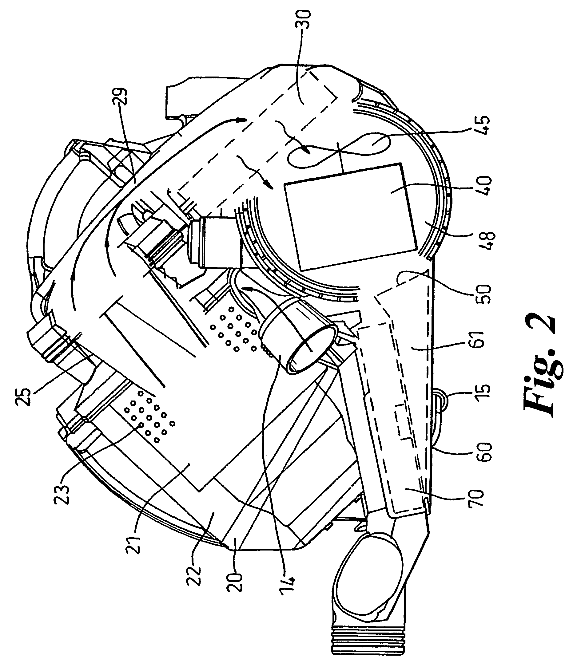
[0025]FIGS. 2 and 3 show some of the internal components of the vacuum cleaner 10 of FIG. 1. The chamber 20 communicates with the inlet 14...


PUM

PropertyMeasurementUnit
acute angleaaaaaaaaaa
widthaaaaaaaaaa
areaaaaaaaaaaa

Abstract

An exhaust assembly for an appliance includes a filter housing for retaining a filter and an exhaust duct which receives airflow from the filter housing. One or more vanes are positioned in the filter housing for guiding airflow from the exhaust side of the filter to the exhaust duct. The vanes spread the airflow entering the exhaust duct across the width thereof so as to reduce noise and to reduce the velocity of the exiting air. The exhaust duct increases in cross-sectional area in the direction of flow through the exhaust duct so as to further reduce the velocity of the exiting air.

Description

FIELD OF THE INVENTION[0001]The invention relates to an exhaust assembly. Particularly, but not exclusively, the invention relates to an exhaust assembly for use in a domestic appliance such as a vacuum cleaner.BACKGROUND OF THE INVENTION [0002]Vacuum cleaners are required to separate dirt and dust from an airflow. Dirt and dust-laden air is sucked into the appliance via either a floor-engaging cleaner head or a tool connected to the end of a hose and wand assembly. The dirty air passes to some kind of separating apparatus which attempts to separate dirt and dust from the airflow. Many vacuum cleaners suck or blow the dirty air through a porous bag so that the dirt and dust is retained in the bag whilst cleaned air is exhausted to the atmosphere. In other vacuum cleaners, cyclonic or centrifugal separators are used to spin dirt and dust from the airflow (see, for example, EP 0 042 723). Whichever type of separator is employed, there is commonly a risk of a small amount of dust passi...

Claims


Application Information

Patent Timeline
Patent Type & Authority Patents(United States)
IPC IPC(8): B01D46/00A47L9/00A47L9/10A47L9/12A47L9/16
CPCA47L9/122A47L9/0081Y10S55/03
Inventor GENN, STUART LLOYDMASON, RICHARD ANTHONY
Owner DYSON TECH LTD
Why Eureka
Try Eureka