Vibration wave motor

a technology of vibration wave and motor, which is applied in the direction of generator/motor, machine/engine, electric generator control, etc., can solve the problems of unconsidered guide mechanism, difficult to thin vibration wave motor, and inconvenient device thinning

Inactive Publication Date: 2008-09-16
CANON KK
View PDF78 Cites 20 Cited by
  • Summary
  • Abstract
  • Description
  • Claims
  • Application Information

AI Technical Summary

Problems solved by technology

However, it is difficult to thin the vibration wave motor.
However, the guide mechanism is not considered.
However, in order to form the closed magnetic circuit, it is necessary to oppose a square U-shaped linear guide and a square U-shaped yoke to each other, so that it is unsuitable to thin the device.
The guide mechanism requires specific parts, which is disadvantageous in cost.
Although a problem does not occur in the case of a rotational motor, when the attractions of the two combined permanent magnets are used in a linear motor, the following problems occur.
When an operation is performed in which the moving member which is stopping in a position shifted from the position in which the magnetic reluctance is a minimum as shown in FIG. 7A is returned toward the position in which the magnetic reluctance is a minimum by a very small amount, there is also a problem in that the moving member overruns an instructed position because of the restoring force F.

Method used


Image

  • Vibration wave motor
  • Vibration wave motor
  • Vibration wave motor

Examples


first embodiment

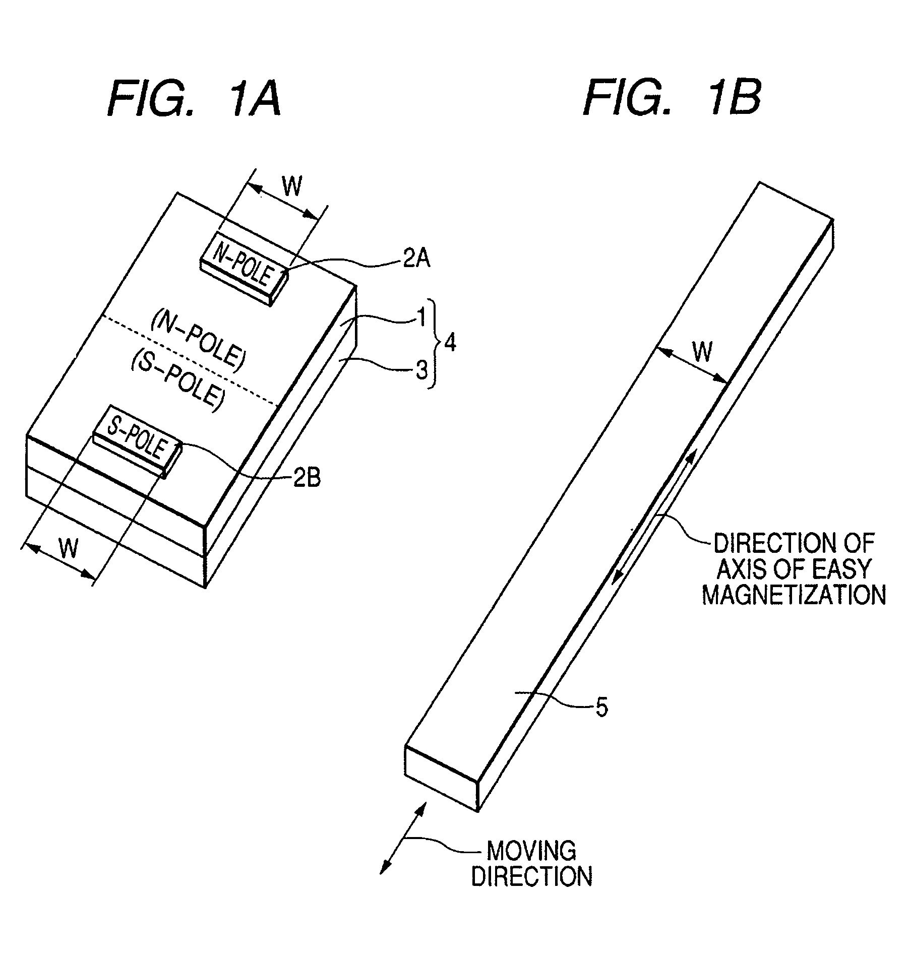
[0035]FIGS. 1A and 1B are perspective views showing a structure of a vibration wave motor according to a first embodiment of the present invention. The vibration wave motor is a linear vibration wave motor. FIG. 1A shows an elastic vibration member and FIG. 1B shows a moving member.

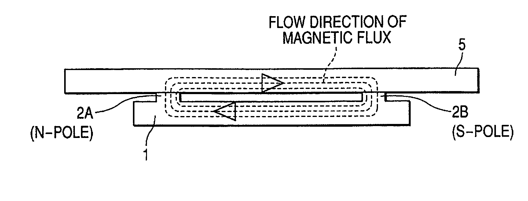
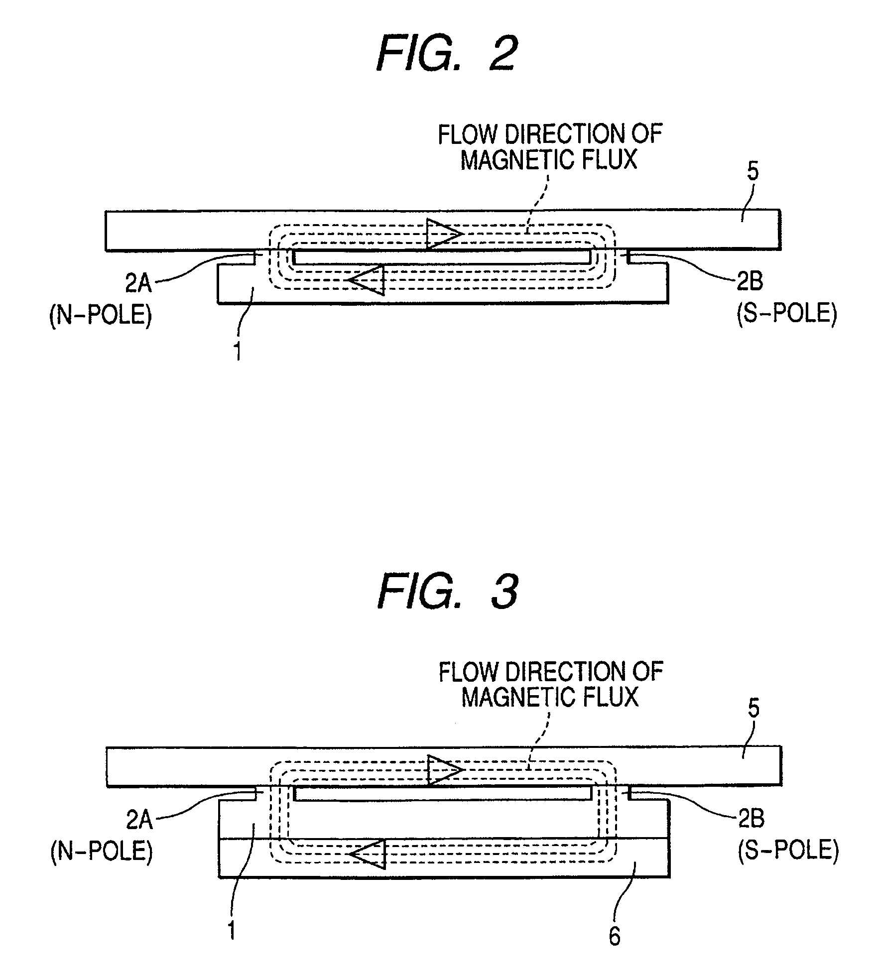
[0036]In FIG. 1A, reference numeral 1 denotes a permanent magnet and 3 denotes a piezoelectric element which acts as an electro-mechanical energy conversion element. An elastic vibration member 4 includes the permanent magnet 1 and the piezoelectric element 3. The permanent magnet 1 is subjected to one-sided two-pole magnetization. A plurality of motion extraction portions 2A and 2B are provided on one surface of the permanent magnet 1 which is subjected to the one-sided two-pole magnetization, and the piezoelectric element 3 is fixed to the other surface thereof by, for example, bonding. The motion extraction portion 2A is magnetized to an N-pole and fixed to an N-pole side of the permanent magnet 1. The...

second embodiment

[0053]FIGS. 4A and 4B are a plan view and a side view, respectively, showing a structure of an elastic vibration member of a vibration wave motor according to a second embodiment of the present invention. The vibration wave motor is a rotational vibration wave motor.

[0054]Reference numeral 11 denotes a disk-shaped permanent magnet and 13 denotes a disk-shaped piezoelectric element. A disk-shaped elastic vibration member 14 includes the disk-shaped permanent magnet 11 and the disk-shaped piezoelectric element 13.

[0055]The disk-shaped permanent magnet 11 is subjected to one-sided four-pole magnetization. A plurality of motion extraction portions 12A, 12B, 12C, and 12D are provided on one surface of the disk-shaped permanent magnet 11 which is subjected to the one-sided four-pole magnetization along a circumferential direction of the disk-shaped permanent magnet 11, and the disk-shaped piezoelectric element 13 is fixed to the other surface thereof by, for example, bonding. The motion e...


PUM


Abstract

Provided is a vibration wave motor including a pressurizing mechanism and a guide mechanism which are used for a moving member and can be thinned. The influence of a restoring force can be eliminated. The vibration wave motor includes an elastic vibration member which is composed of a permanent magnet and a piezoelectric element which are fixed to each other, a plurality of motion extraction portions provided on the permanent magnet, and a moving member which is pressurized to be in contact with the plurality of motion extraction portions. A closed magnetic circuit of a magnetic flux is formed to connect between the elastic vibration member and the moving member through the plurality of motion extraction portions. A flow direction of the magnetic flux passing through the moving member is aligned with a moving direction of the moving member.

Description

BACKGROUND OF THE INVENTION[0001]1. Field of the Invention[0002]The present invention relates to a vibration wave motor, and more particularly, to a vibration wave motor for driving a moving member by an elastic vibration member excited with a plurality of vibration modes.[0003]2. Related Background Art[0004]Up to now, the following vibration wave motors have been known. In the vibration wave motors, a plurality of vibrations obtained with a plurality of vibration modes are synthesized and a plate-shaped elastic vibration member is driven by the synthesized vibrations, thereby driving a moving member which is pressurized against the elastic vibration member into frictional contact therewith. As a representative example of the vibration wave motors, JP 6-311765 A discloses a vibration wave motor in which two bending vibration modes are synthesized.[0005]In addition, JP 7-143771 A discloses a vibration wave motor in which a longitudinal vibration mode and a bending vibration mode are ...

Claims


Application Information

Patent Timeline
Patent Type & Authority Patents(United States)
IPC IPC(8): H02P9/04H01L41/00H02N2/00
CPCH02N2/163
Inventor SUZUKI, MASAHARU
Owner CANON KK
Why Eureka
Try Eureka