Moving body system

a body system and moving body technology, applied in the direction of instruments, programme control, roads, etc., can solve the problems of serious time loss, vehicle b>101/b> starts to decelerate prematurely, and is likely to slip, so as to improve workability, more reliable, and reliable

Inactive Publication Date: 2008-09-16
MURATA MASCH LTD
View PDF112 Cites 16 Cited by
  • Summary
  • Abstract
  • Description
  • Claims
  • Application Information

AI Technical Summary

Benefits of technology

[0012]With the latter conventional technique (the Unexamined Japanese Patent Application Publication (Tokkai) No. 2002-351541), there is only a short distance between the stop position 208 and the position immediately before the stop position 208. Accordingly, there is only a small difference between the actual running distance and the running distance obtained by accumulating output pulses from the encoder on the basis of the detection of the trailing end of the marker 220 at the position 207. This substantially avoids the disadvantageous situation in which the vehicle 201 starts to decelerate prematurely and in which it thus takes the vehicle 201 too long a time to reach the destination, as in the case of the conventional technique. The vehicle 201 can also move fast between the position 207 and the stop position 208. Further, the vehicle 201 can be precisely stopped at the stop position 208.
[0029]Moreover, with the aspect of the present invention set forth in claim 5, every time the detecting means detects the detecting point on the mark member of the detected member, the control means resets the measurement of the moving distance by the encoder to the origin. This makes it possible to carry out measurement of the moving distance without being affected by errors from previous operations. The moving body system is thus more reliable.

Problems solved by technology

In particular, a slip is likely to occur when the vehicle 101 is accelerated or decelerated.
As a result, the vehicle 101 starts to decelerate prematurely.
However, such an approach requires a long time, resulting in a serious time loss.
This disadvantageously degrades the workability of the system.
. . When the vehicle 201 is stopped at other positions, such problems as associated with the former conventional technique may occur.
. . This checking operation requires much time and effort and is cumbersome.

Method used


Image

  • Moving body system
  • Moving body system
  • Moving body system

Examples


Embodiment Construction

[0030]A moving body system according to the present invention will be described below with reference to an automated guided vehicle system by way of example.

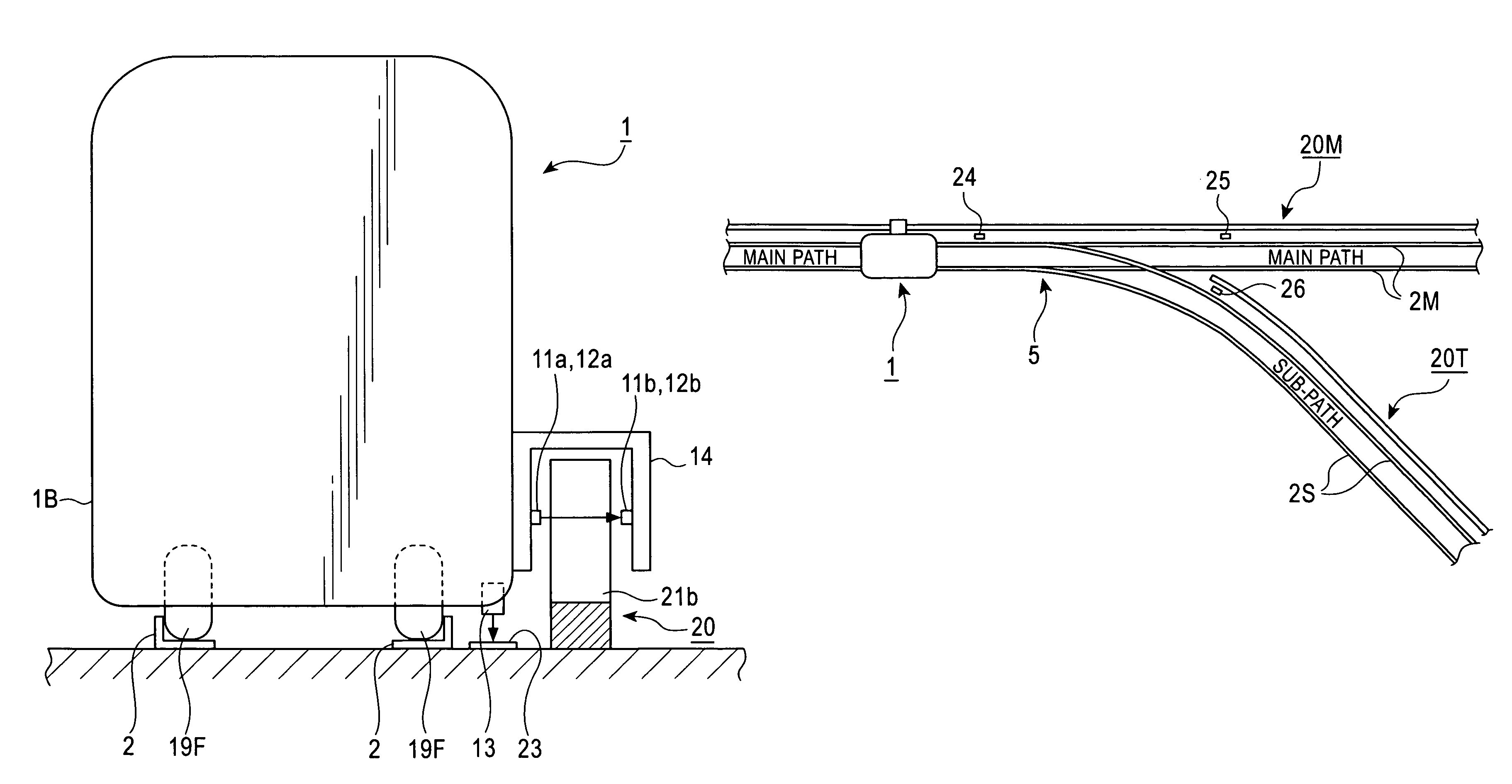
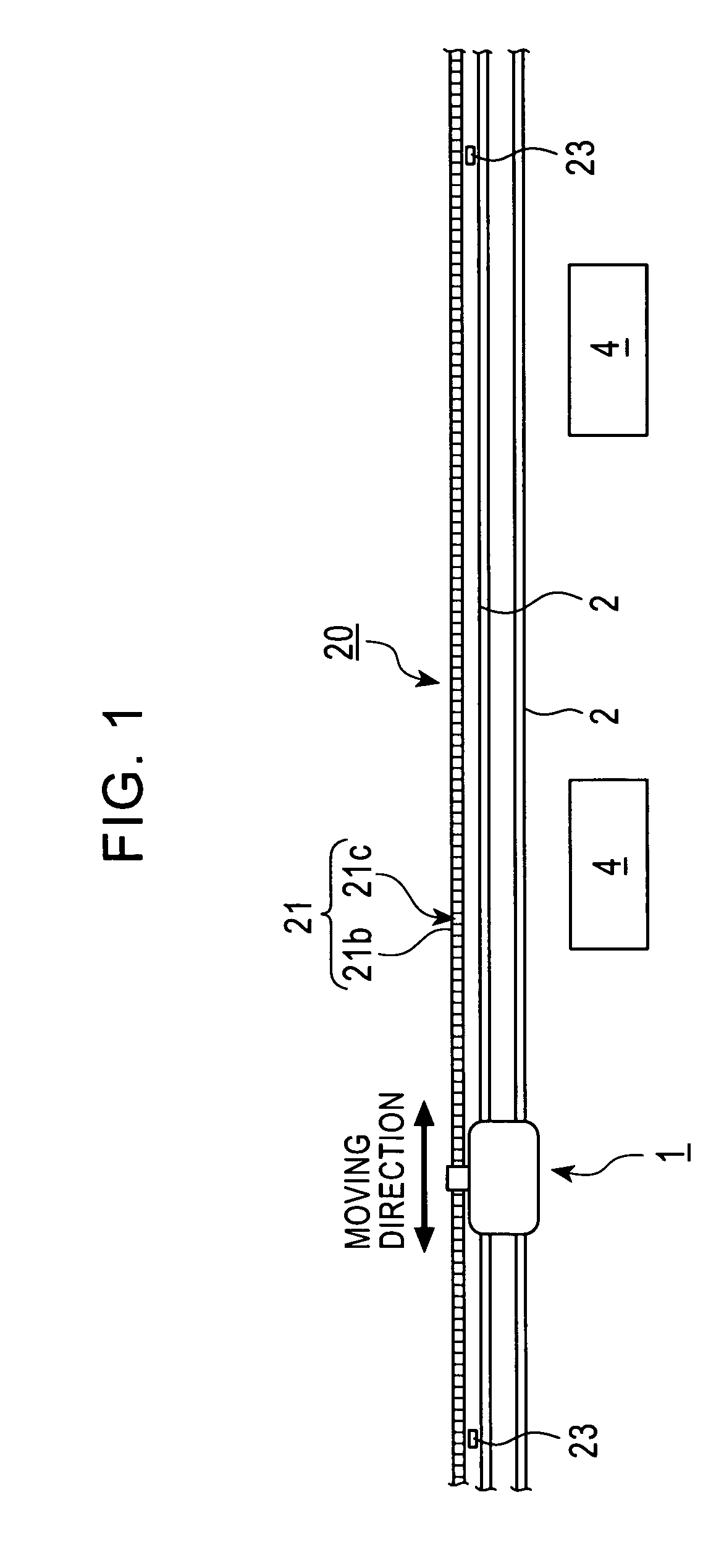
[0031]FIG. 1 generally shows the configuration of the automated guided vehicle system. In a clean room of a semiconductor manufacturing plant or the like, running rails 2, 2 are laid as a moving path of an automated guided vehicle 1. Processing devices 4, 4, . . . and the like are arranged along the running rails 2, 2. A detected member 20 is also laid along the running rails 2. The vehicle 1 running on the running rails 2, 2 determines its own running position while detecting the detected member 20. According to the present embodiment, the detected member 20 is placed outside one 2 of the running rails 2, 2. However, the detected member 20 may be placed between the running rails 2, 2 or installed above the running rails 2, 2. The arrangement of the detected member 20 is not particularly limited provided that it is extended alon...


PUM


Abstract

It is an object of the present invention to provide a moving body system which can determine the moving position of a vehicle, stacker crane, or other moving body wherever on a moving path having a branching portion or a joining portion the moving body is, the system being able to precisely stop the moving body at any position and enabling the moving body to move fast to a stop position. A moving body system includes a vehicle 1 moving along running rails 2, 2 constituting a moving path having a joining portion and a detected member 20 laid along the running rails 2, 2. The detected member 20 includes a large number of mark members 21, 21, . . . in a direction in which the vehicle 1 moves. The vehicle 1 includes a first detecting sensor 11 and a second detecting sensor 12 which detect the mark members of the detected member 20.

Description

FIELD OF THE INVENTION[0001]The present invention relates to a moving body system that moves a moving body along a moving path.SUMMARY OF THE INVENTION[0002]A known automated guided vehicle system is used in a semiconductor manufacturing plant or the like, and in the automated guided vehicle system, a moving path is laid along processing devices and the like. An automated guided vehicle is caused to run automatically on the moving path to convey work pieces. The automated guided vehicle needs to be precisely stopped in front of a processing device. The automated guided vehicle system is configured as described below.[0003]FIG. 14 is a diagram generally showing the configuration of a conventional automated guided vehicle system. Processing devices 104, 104, . . . are arranged along a running path 102 of an automated guided vehicle 101. Stop position marks 120 are stuck to respective stop positions of the vehicle 101 which correspond to the processing devices 104, 104, . . . and the l...

Claims


Application Information

Patent Timeline
Patent Type & Authority Patents(United States)
IPC IPC(8): E01B25/06B61L23/00B61L25/02B61L27/04G01D5/245
CPCB61L23/005G01D5/2457B61L27/04B61L25/026
Inventor MORIGUCHI, TOSHIKI
Owner MURATA MASCH LTD
Why Eureka
Try Eureka