Tufting machine and process for variable stitch rate tufting

a tufting machine and variable stitch technology, applied in the field of tufting machines, can solve the problems of not being able to provide for different length stitches within the same pattern without utilizing, and being difficult to change the number of stitches per inch being sewn by the tufting machine,

Inactive Publication Date: 2008-09-23
TUFTCO
View PDF8 Cites 39 Cited by
  • Summary
  • Abstract
  • Description
  • Claims
  • Application Information

AI Technical Summary

Benefits of technology

[0008]It is further an object of the present invention to provide a tufting machine in which the stitch rate may be varied without altering the stitch density of the tufted fabric.

Problems solved by technology

As a result, it was traditionally difficult to change the number of stitches per inch being sewn by the tufting machine, for instance, to arrive at a pre-determined weight for a square yard of carpet.
Furthermore, it was practically impossible to provide for different length stitches within the same pattern without utilizing crammed sheaves or other notoriously complicated mechanical arrangements such as described in Ingram, et al., U.S. Pat. No. 4,577,208.
These arrangements provided no means for fine tuning the lengths of the varied stitches in the pattern as is typically required if two rows of needles are utilized in the pattern.
Also the sheer complexity of the arrangements generally has required operation of conventional tufting machines at slower speeds, and has provided only limited pattern variations.
While these computer controlled servo motor driven backing feed rolls have provided a straightforward solution to the problem of changing stitch density, and have provided greater versatility in controlling the backing feed, they did not suggest utilizing a variable stitch rate in tufting fabrics.

Method used


Image

  • Tufting machine and process for variable stitch rate tufting
  • Tufting machine and process for variable stitch rate tufting
  • Tufting machine and process for variable stitch rate tufting

Examples


Embodiment Construction

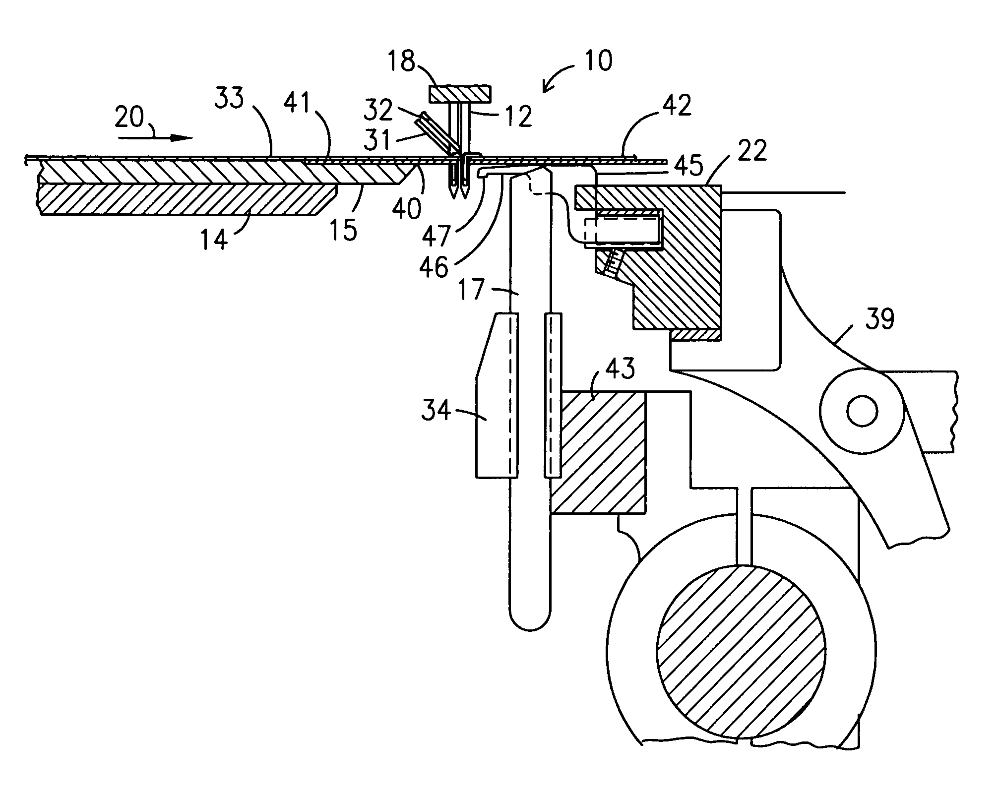
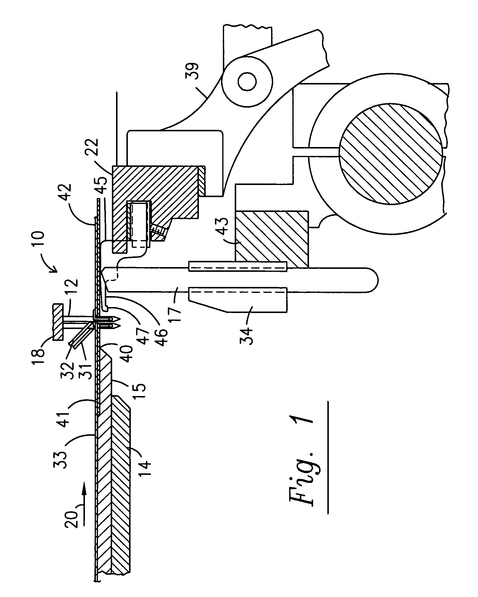
[0019]Turning first to FIG. 1, a representative cut pile tufting machine 10 with staggered needle bar 18 is shown. The staggered needle bar 18 supports a first row of uniformly spaced rear needles 12 and a second row of uniformly spaced front needles 11 offset midway between the rear needles 12, to provide a uniform narrow gauge staggered needle tufting machine 10. It will be understood that the invention may also be practiced with two independent needle bars, each supporting a row of needles, and each shift able to either place the needles on the front and rear needle bars directly in line or offset as desired. The needle bar 18 is vertically reciprocated by conventional means, not shown, to cause the front and rear needles 11, 12 to move between an upward position, not shown, above the base fabric 33 and a downward position so that the needles will carry front yarns 31 and rear yarns 32 through the base fabric 33 to form loops of tufting therein. The base fabric 33 is supported up...


PUM


Abstract

A tufting machine as disclosed with a variable yarn feed mechanism and a method for tufting patterns with yarns from two rows of needles offset longitudinally from one another in a fashion that the different stitch lengths are selected in a fashion that the yarns from each row of needles are complementary to the other and maintain a consistent stitch density.

Description

[0001]The present application claims priority to the Oct. 5, 2004 filing date of U.S. provisional patent application Ser. No. 60 / 615,982.FIELD OF THE INVENTION[0002]This invention relates to a tufting machine, and is more particularly concerned with a tufting machine having a servo motor controlled backing feed mechanism and a method for varying the length of selected stitches in a pattern design and creating novel tufted fabrics that simulate woven fabric designs.BACKGROUND OF THE INVENTION[0003]A tufting machine, especially a tufting machine adapted for the manufacture of carpet, has a pair of pin rollers which are driven to feed a primary backing material off of a large storage roll and over a bed frame. The two pin rollers are disposed on opposite sides of the bed frame so that the first pin roller introduces the primary backing material into the tufting machine, and the second pin roller removes the backing material from the tufting machine. A set of needles are located above t...

Claims


Application Information

Patent Timeline
Patent Type & Authority Patents(United States)
IPC IPC(8): D05C15/12D05C15/14
CPCD05C15/26D05C15/14
Inventor SMITH, JEFFBISHOP, MIKELOVELADY, BRIANRUMFOLA, ROBERTA M.
Owner TUFTCO
Why Eureka
Try Eureka