Large collection angle x-ray monochromators for electron probe microanalysis

Inactive Publication Date: 2008-09-23
KLA TENCOR TECH CORP
View PDF1 Cites 6 Cited by
  • Summary
  • Abstract
  • Description
  • Claims
  • Application Information

AI Technical Summary

Benefits of technology

[0069]The solution of this equation produces a family of solutions parameterized by the constant g. These solutions allow efficient reflection over the entire reflector as long as the scan distance, a, is much smaller than the nominal working distance, w0.
[0070]A non-focusing multilayer optic of the types described herein may be used as monochromators in an x-ray detection sub-assembly of an EPMA. Radially or axially scannable non-focusing x-ray monochromators as described herein may obviate the need for multiple reflectors thereby allowing for a turret-less monochromator while retaining the energy scanning capabilities of a multiple system. The freedom of shape possible with non-focusing optics allows for one or more of larger collected solid angle, scanability, and angular detection. Use of non-focusing x-ray optics in EPMA systems would enable higher precision and faster throughput of EPMA applications to thin film measurement in semiconductor fabrication. Such embodiments of the present invention would enable the background level around an emission line to be measured and therefore increase the accuracy and matching of EPMA applications. Such embodiments of the present invention would also aid in the measurement of concentration depth profiles by the use of emission angle information. Non-focusing x-ray monochromators of t

Problems solved by technology

Unfortunately, the turret design places geometrical restrictions on the number of large solid angle reflectors that can be accommodated by the turret.
Prior art x-ray detection systems suffer from other drawbacks.
Unfortunately, a circular cylindrical reflector is not an optimum shape to achieve the best

Method used


Image

  • Large collection angle x-ray monochromators for electron probe microanalysis
  • Large collection angle x-ray monochromators for electron probe microanalysis
  • Large collection angle x-ray monochromators for electron probe microanalysis

Examples


Embodiment Construction

[0022]Although the following detailed description contains many specific details for the purposes of illustration, anyone of ordinary skill in the art will appreciate that many variations and alterations to the following details are within the scope of the invention. Accordingly, the exemplary embodiments of the invention described below are set forth without any loss of generality to, and without imposing limitations upon, the claimed invention.

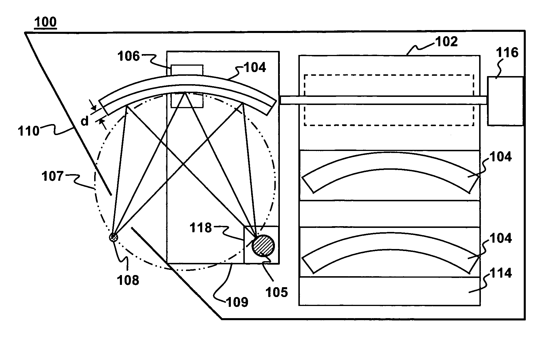
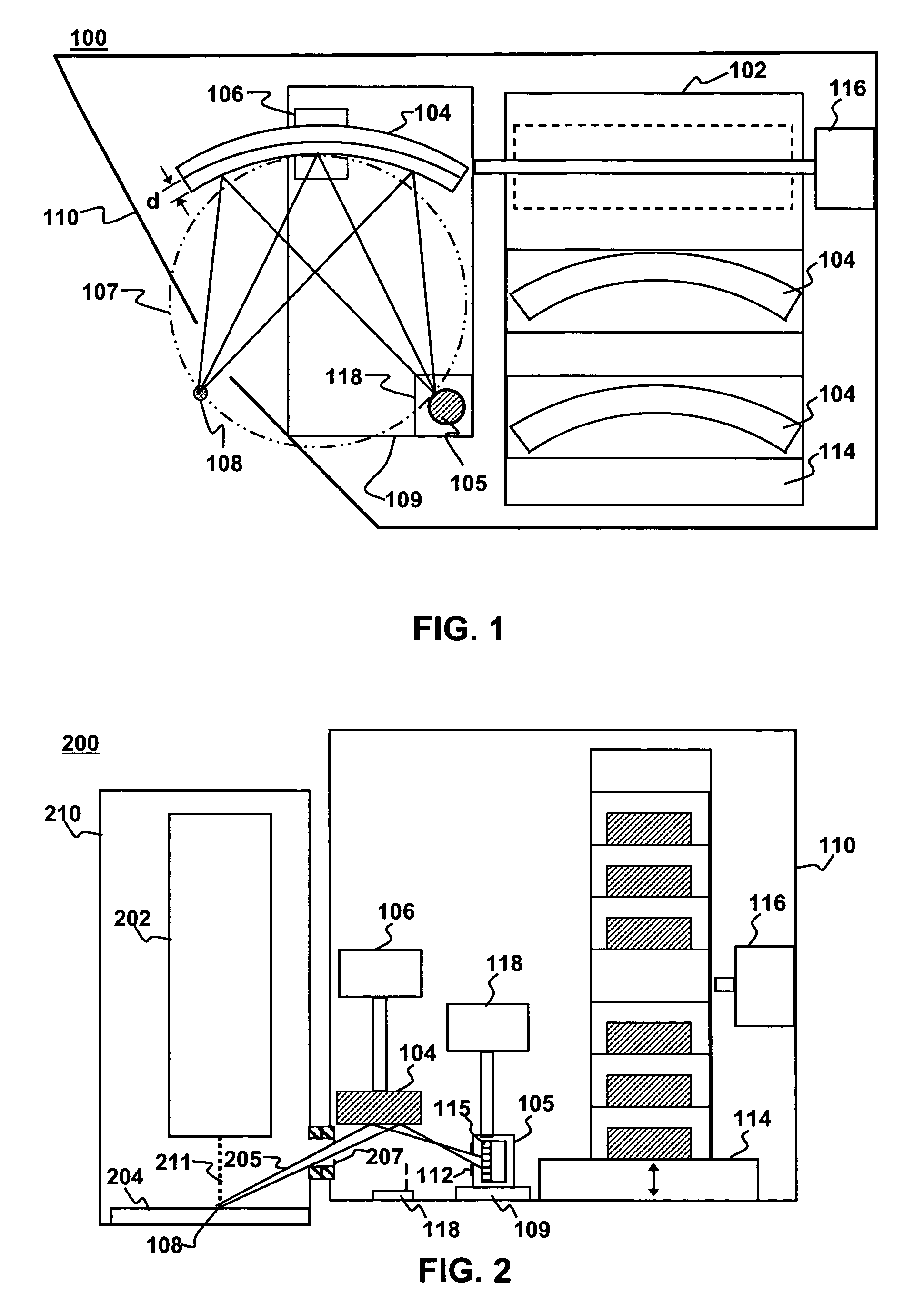
[0023]As illustrated, e.g., in FIG. 1 and FIG. 2, certain embodiments of the present invention use a cassette of reflectors instead of a turret. FIG. 1 depicts an x-ray monochromator 100 according to a first embodiment of the present invention. The monochromator includes a cassette 102 adapted to retain multiple x-ray reflectors 104 and an x-ray detector 105. A positioning mechanism 106 selects a reflector 104 from the cassette 102 and rotates it into position for reflection of x-rays from a known location 108 toward the detector 105. With t...


PUM


Abstract

X-ray monochromators and electron probe micro-analysis (EPMA) systems using such monochromators are disclosed. A turretless x-ray monochromator may have a cassette of reflectors instead of a turret. The cassette stores a plurality of reflectors that can be inserted into a conventional Rowland circle monochromator geometry. A transfer mechanism selectively moves reflectors from the cassette to a reflector positioner. The use of the cassette allows each reflector to be placed closer to a source of x-rays, thereby allowing a larger solid angle for x-ray collection. An alternative x-ray monochromator uses a non-focusing reflector that can be fixed, scanned axially or scanned radially to provide large solid angle detection of x-rays at various energies with a single reflector.

Description

FIELD OF THE INVENTION[0001]This invention generally relates to electron probe micro-analysis (EPMA). More particularly, this invention relates to analyzing the properties, such as thickness and composition, of a sample, such as layers used to form integrated circuits on a semiconducting substrate.BACKGROUND OF THE INVENTION[0002]Integrated circuit fabrication is typically accomplished by forming many different layers on a substrate. As used herein, the phrase integrated circuit refers to circuits such as those formed on monolithic substrates of a semiconducting material, such as group IV materials like silicon and germanium, and group III-V compounds such as gallium arsenide. Because the design tolerances of an integrated circuit are so strict, it is desirable to monitor the properties, such as thickness and elemental composition, of the various layers as they are formed. One way to measure the properties of film layers is to use electron microprobe x-ray spectrometry.[0003]Electro...

Claims


Application Information

Patent Timeline
IPC IPC(8): G01N23/00G21K7/00
CPCG21K1/06H01J37/244H01J37/252H01J2237/2561H01J2237/24425
Inventor JANIK, GARY R.MOORE, JEFFREY A.
Owner KLA TENCOR TECH CORP
Why Eureka
Try Eureka