
Dual polarization antenna and RFID reader employing the same

a dual-polarization antenna and reader technology, applied in the direction of polarised antenna unit combinations, resonant antennas, antenna earthings, etc., can solve the problem of limited communication distance, and achieve excellent orthogonal characteristics, extend the transmission distance between the reader, and high isolation characteristics

Inactive Publication Date: 2008-09-23
ELECTRONICS & TELECOMM RES INST
View PDF5 Cites 33 Cited by
  • Summary
  • Abstract
  • Description
  • Claims
  • Application Information

AI Technical Summary

Benefits of technology

The present invention provides a dual polarization antenna that can extend the distance between a reader and a tag with excellent isolation and communication quality. The antenna has a high degree of freedom in designing and manufacturing. It includes four inverted F-type radiators that form an angle of 90 degrees with each other. The currents of the same phase are fed to the first and second radiators, and the currents of inverted phases are fed to the third and fourth radiators. The antenna has a unique feeding path length difference between the first and second radiators, and between the third and fourth radiators. This results in high isolation and reduced interference between the two polarizations. The invention also provides an RFID reader that includes the dual polarization antenna and signal processing block for processing transmitted / received RF signals. The reader has improved communication quality with RFID tags.

Problems solved by technology

Therefore, since the conventional dual polarization antenna is more likely to induce a bit error by lowering a received power in a communication link between the reader and the tag due to a low isolation characteristic, a communication distance can be limited.

Method used


Image

  • Dual polarization antenna and RFID reader employing the same
  • Dual polarization antenna and RFID reader employing the same
  • Dual polarization antenna and RFID reader employing the same

Examples


Embodiment Construction

[0024]Other objects and advantages of the present invention will become apparent from the following description of the embodiments with reference to the accompanying drawings. Therefore, those skilled in the art that the present invention is included can embody the technological concept and scope of the invention easily. In addition, if it is considered that detailed description on the prior art may blur the points of the present invention, the detailed description will not be provided herein. The preferred embodiments of the present invention will be described in detail hereinafter with reference to the attached drawings.

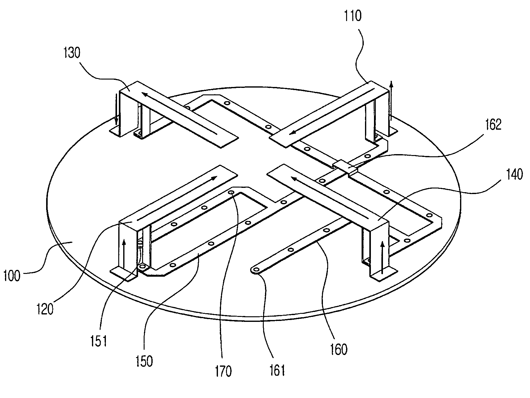
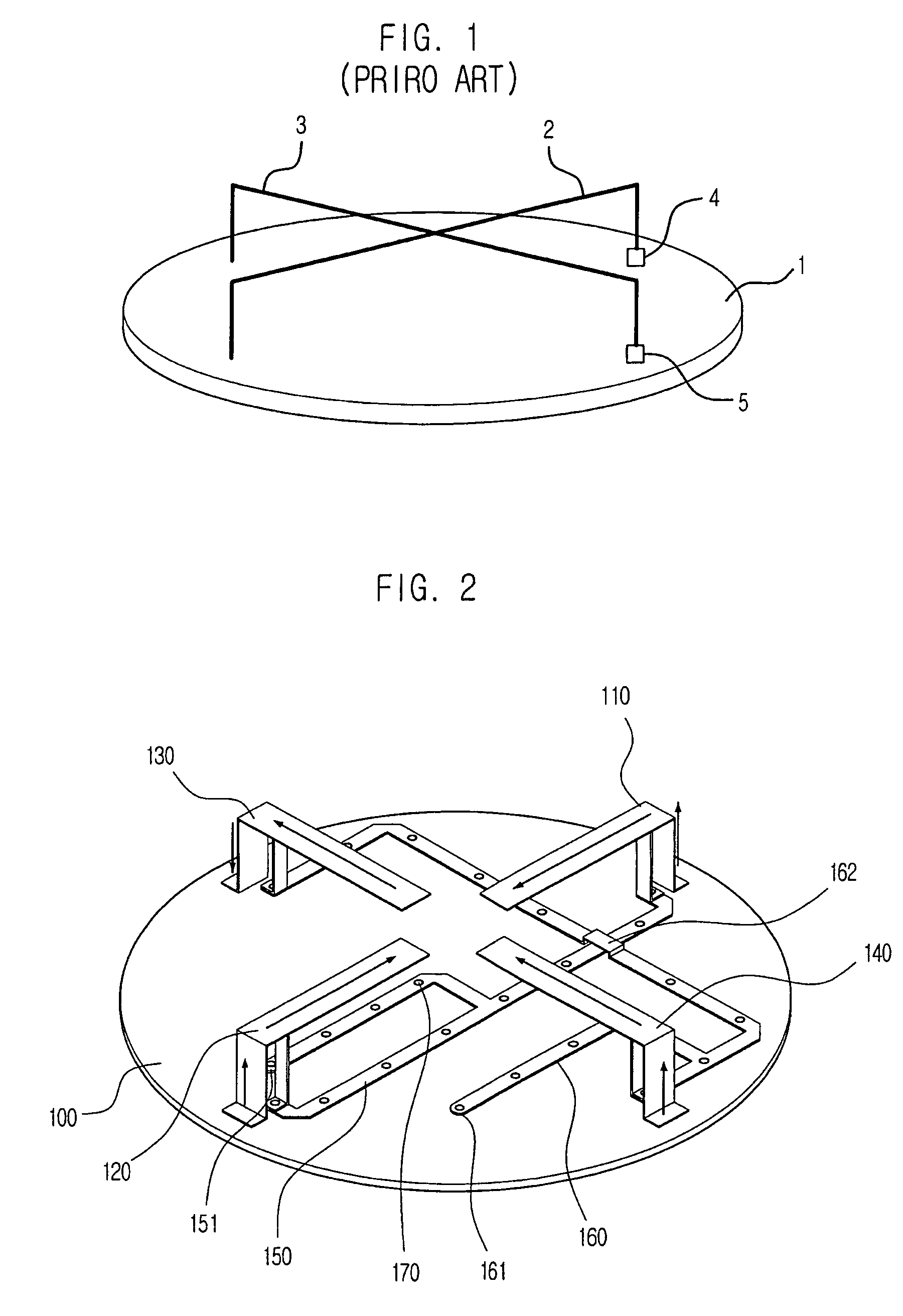
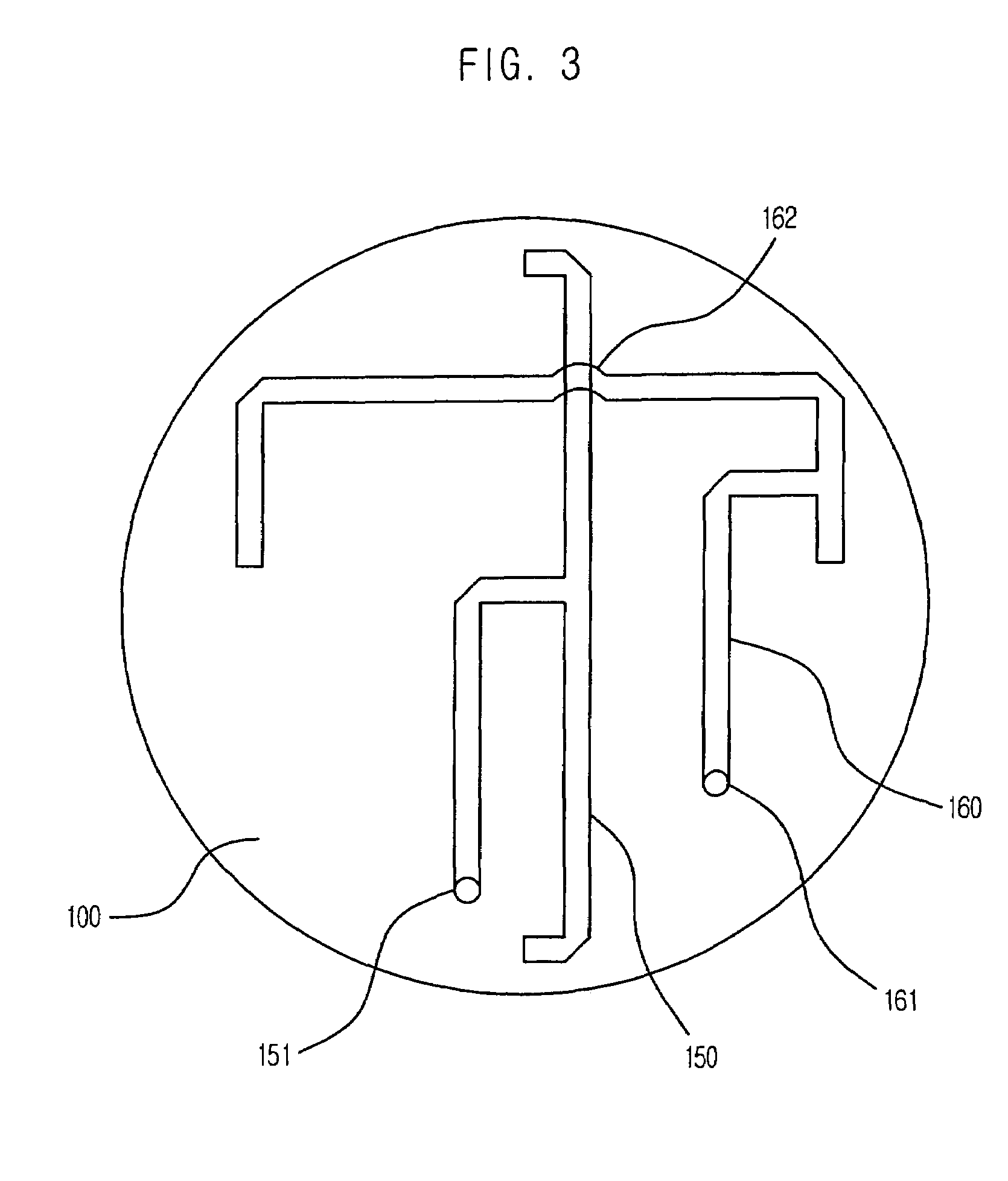
[0025]FIG. 2 is a perspective view showing an antenna using four inverted F-type radiators in accordance with an embodiment of the present invention. First, second, third and fourth inverted F-type radiators 110, 120, 130 and 140 are positioned on top of a circular ground plate 100. The four inverted F-type radiators are metal strips and maintain an angle of 90° to...


PUM


Abstract

Provided is a dual polarization antenna realized by using four inverted F-type radiators and a Radio Frequency Identification (RFID) reader employing the dual polarization antenna. The dual polarization antenna includes a ground plate and four inverted F-type radiators set up on the ground plate. Currents of the same phase are fed to the first and second inverted F-type radiators each other. Currents of an inverted phase are fed to the third and fourth inverted F-type radiators each other. The four inverted F-type radiators form an angle of 90° with one another. The first and second inverted F-type radiators radiate electric wave of vertical polarization and the third and fourth inverted F-type radiators radiate electric wave of horizontal polarization. Since the dual polarization antenna has excellent orthogonal and isolation characteristics, the antenna can extend a transmission distance between the reader and the tag and improve a communication quality.

Description

FIELD OF THE INVENTION[0001]The present invention relates to a dual polarization antenna and a radio frequency identification reader employing the same; and, more particularly, to a dual polarization antenna realized by using four inverted F-type radiators and a Radio Frequency Identification (RFID) reader employing the dual polarization antenna.DESCRIPTION OF RELATED ART[0002]A dual polarization antenna radiating electromagnetic wave having two polarization characteristics should have an orthogonal characteristic between ports. Generally, the dual polarization antenna should have an input standing wave ratio of less than 1.5 and isolation of more than 25 dB between vertical and horizontal polarization ports. Also, the dual polarization antenna should have a gain of 3±1 dB since a wireless communication section between a reader and a tag has a non-directional characteristic in a Radio Frequency Identification (RFID) system.[0003]A conventional dual polarization antenna includes two ...

Claims


Application Information

Patent Timeline
Patent Type & Authority Patents(United States)
IPC IPC(8): H01Q1/38
CPCH01Q1/22H01Q1/2216H01Q21/24H01Q21/065H01Q9/0421
Inventor CHOI, WON-KYUSEONG, NAK-SEONPYO, CHEOL-SIGCHAE, JONG-SUK
Owner ELECTRONICS & TELECOMM RES INST
Learn More