Wideband floating wire antenna using a double negative meta-material

a floating wire antenna and double negative technology, applied in the field of underwater vehicle communication, can solve the problems of limited performance and prior art antennas suffering from limited performance in the commercial high frequency (hf) band of 2 to 30 mhz, and achieve the effect of improving performance in the commercial hf band

Inactive Publication Date: 2008-09-30
UNITED STATES OF AMERICA
View PDF11 Cites 6 Cited by
  • Summary
  • Abstract
  • Description
  • Claims
  • Application Information

AI Technical Summary

Benefits of technology

The present invention aims to improve the performance of a buoyant cable antenna element in the commercial HF band. The technical effect is to enhance the efficiency and performance of the antenna element in the commercial HF band.

Problems solved by technology

The technical problem addressed in this patent text is the limited performance of prior art buoyant cable antennas in the commercial high frequency (HF) band of 2 to 30 MHZ due to the limited band width of the prior art antenna elements. There is a need for a buoyant cable antenna element that can improve the bandwidth of the antenna in the HF band.

Method used


Image

  • Wideband floating wire antenna using a double negative meta-material
  • Wideband floating wire antenna using a double negative meta-material
  • Wideband floating wire antenna using a double negative meta-material

Examples


Embodiment Construction

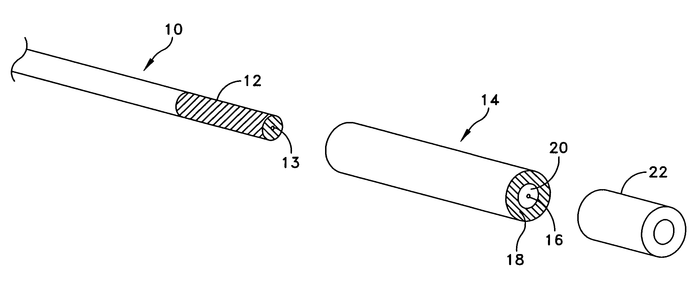
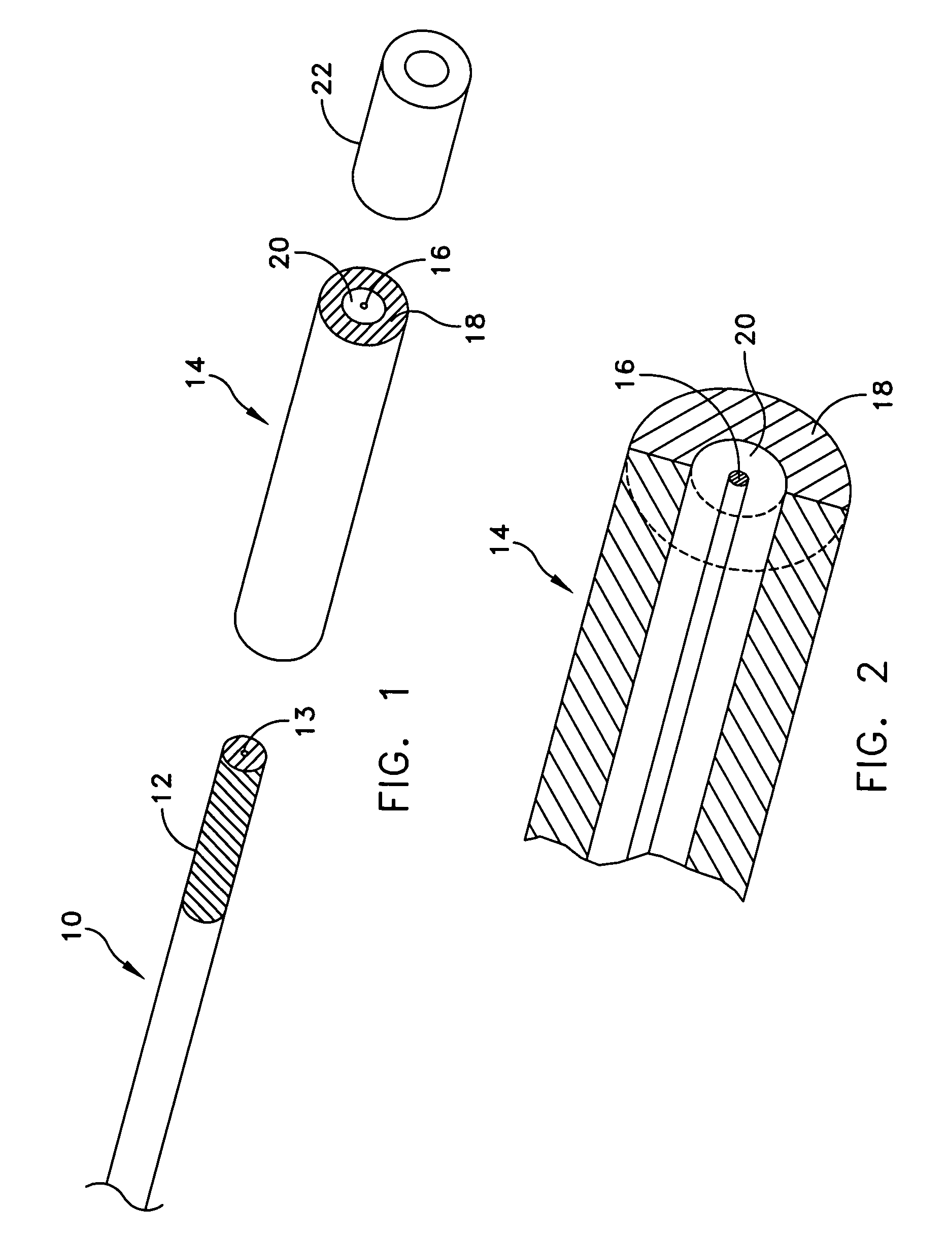
[0013]Referring to FIG. 1, there is illustrated an exploded view of the present invention. Using the geometry of prior art buoyant cable antennas as a point of departure there is illustrated a coaxial feed line 10. The coaxial feed line 10 is a standard 50 ohm transmission line, however, the invention is not limited to use with a 50 ohm transmission lines. At the end of the coaxial feed line 10 the braid 12 is exposed for 3 to 4 inches. This is necessary in order to ground the feed system for the antenna. At the end of the section of exposed braid 12 the center conductor 13 of coaxial feed line 10 is connected to the antenna element 14. The antenna element 14 is designed to be positively buoyant and to float on the surface of a body of water. The antenna element 14 consist of a straight wire 16, usually a copper (or other metal) conductor of uniform diameter along its length. The straight wire 16 may be either a solid or stranded copper conductor. The antenna element 14 has a cylind...


PUM


Abstract

A buoyant cable antenna element is taught that employs a specific double-negative meta-material sheath with a negative permeability. The double-negative meta-material sheath is disposed over the insulated wire portion of the buoyant cable antenna element. The double-negative meta-material sheath enables a deliberate reduction in the antenna wire inductance to a zero value at a desired critical frequency. Reducing the antenna wire inductance to zero creates a traveling wave structure antenna having enhanced bandwidth.

Description


Claims


Application Information

Patent Timeline
Owner UNITED STATES OF AMERICA
Why Eureka
Try Eureka