AI technical title is built by Patsnap AI team. It summarizes the technical point description of the patent document.
a technology for generators and power supplies, applied in the control of electric generators, renewable energy generation, final product manufacturing, etc., can solve the problems of windmill parts being blown off, and achieve the effect of cost reduction and cost reduction
Inactive Publication Date: 2008-10-07
SHINKO ELECTRIC CO LTD
View PDF23 Cites 10 Cited by
Summary
Abstract
Description
Claims
Application Information
AI Technical Summary
This helps you quickly interpret patents by identifying the three key elements:
Problems solved by technology
Method used
Benefits of technology
Benefits of technology
The present invention provides an electric generator that can solve problems of high cost and difficulty in assembly. The electric generator includes a rotatable shaft, a rotator, a clutch, a housing, and a stator. The stator is fixed to the housing and located opposite to the rotator. This design eliminates the need for separate parts and simplifies the assembly process. The electric generator can also be designed with a divided stator core, making it easier to assemble and wind a coil around. Additionally, the electric generator can be designed to protect against excessive rotation and damage by stopping the driving power generating unit. The electric generator can also output electricity with a high voltage using a natural energy source.
Problems solved by technology
For example, in the case where a windmill is rotated by wind power, which is a form of natural energy, to generate electricity by the rotational energy of the windmill, the rotation of the windmill is stopped in an unusual situation, and therefore it is possible to avoid the windmill breaks down, resulting, for example, in a danger that a parts of the windmill will be blown off.
Method used
Image
Click on the blue label to locate the original text in one second.
Reading with bidirectional positioning of images and text.
Examples
Embodiment Construction
[0029]In what follows, a wind power electric generator according to an embodiment of the present invention will be specifically explained while the present invention is not limited to the embodiment.
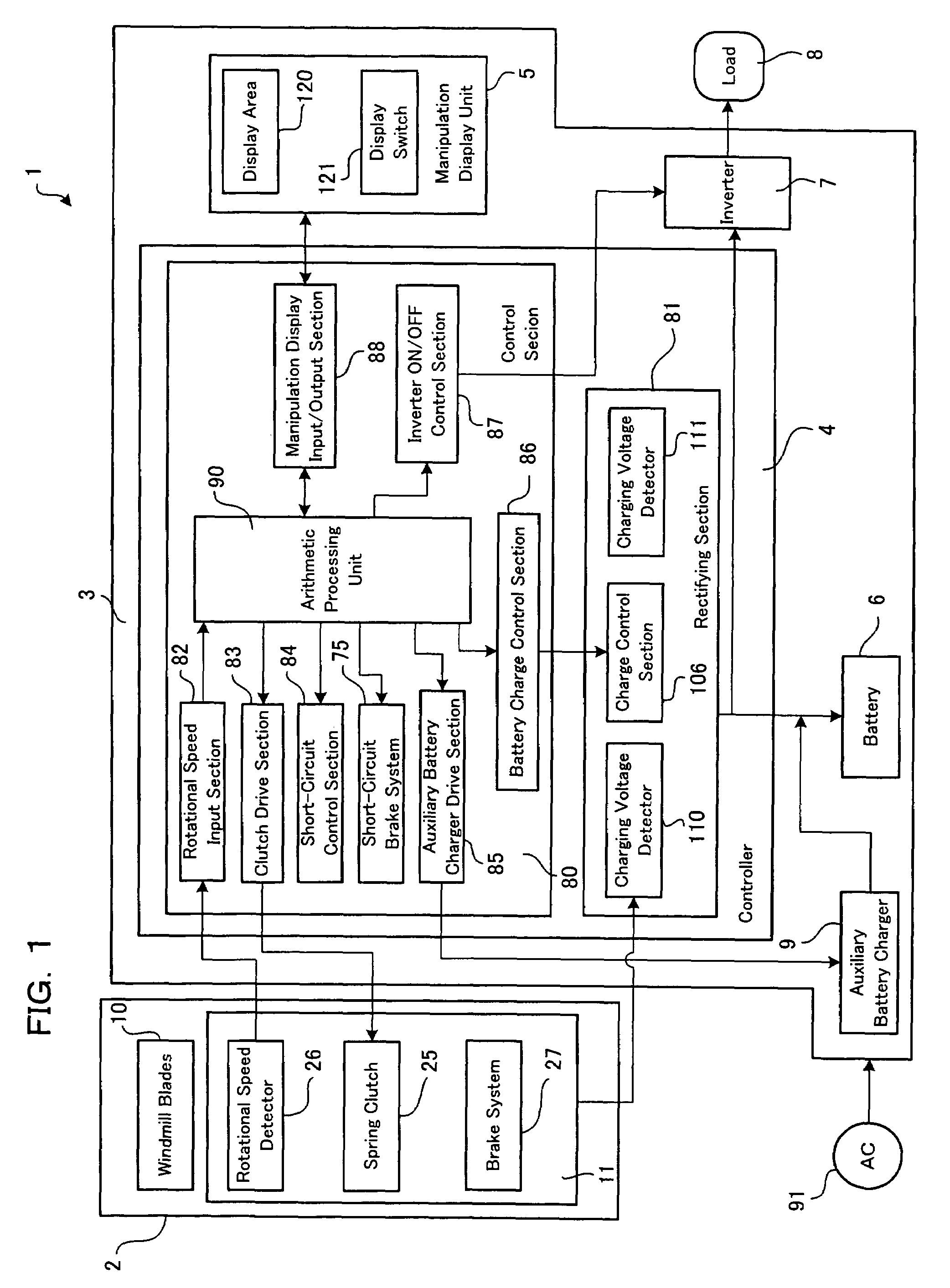
[0030]FIG. 1 is a block diagram showing the wind power electric generator according to the preferred embodiment of the present invention. In FIG. 1, the wind power electric generator 1 according to the present embodiment is a vertical axis type wind power electric generator comprising a wind power electric generator main body 2 for outputting an AC power by converting wind power energy as a form of natural energy into electric energy, and a power supply equipment 3 for controlling the wind power electric generator main body 2 and displaying the setting thereof.
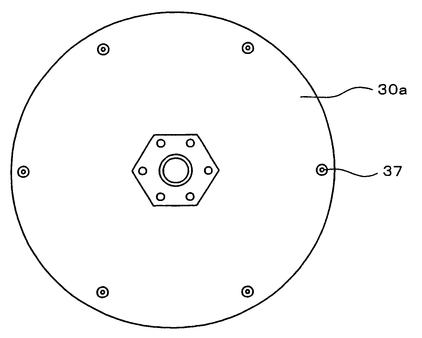
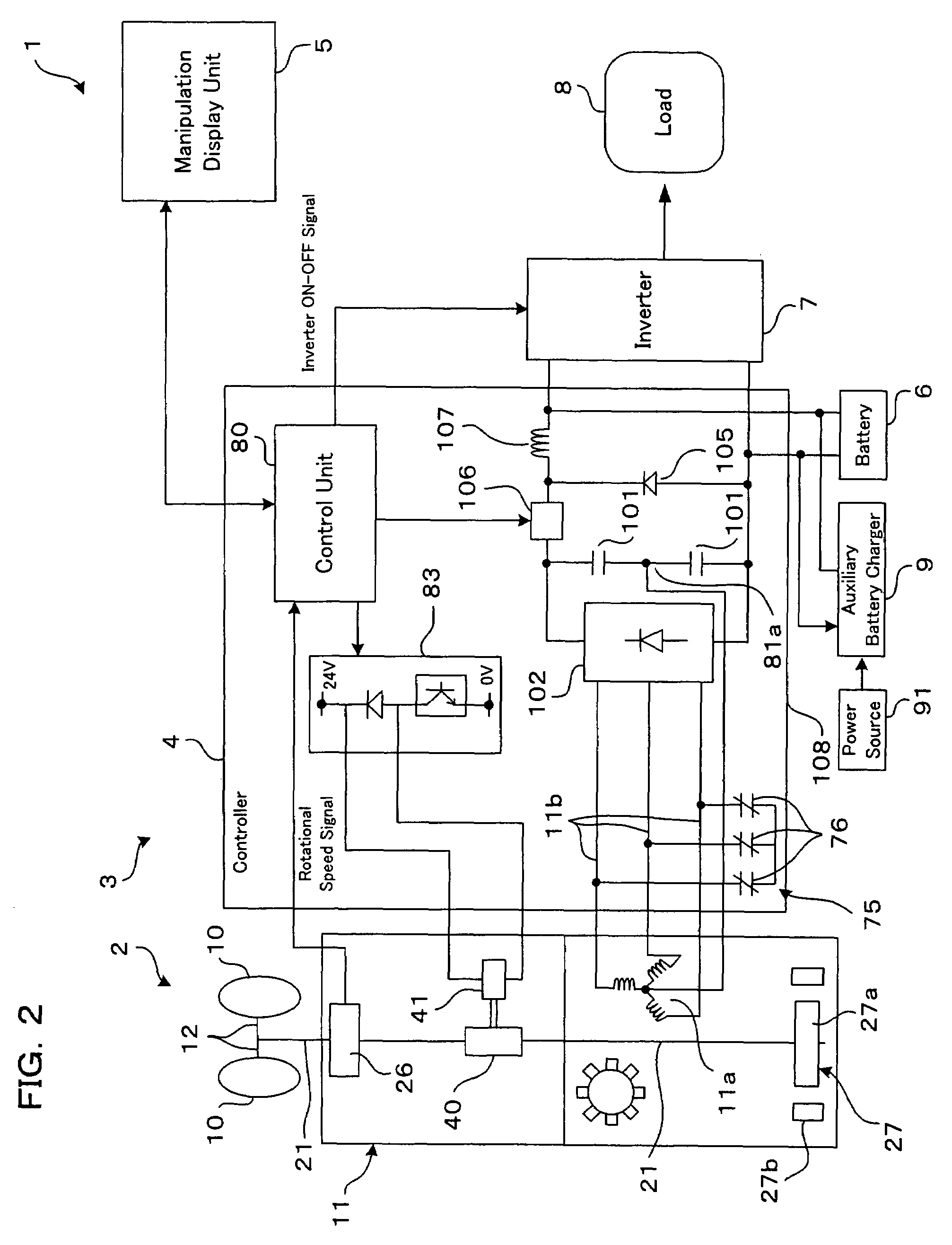
[0031]First, the wind power electric generator main body 2 will be explained with reference to FIG. 2 and FIG. 3. In the figures, FIG. 2 is a schematic diagram showing the overall configuration of the...
PUM
Property
Measurement
Unit
torque
aaaaa
aaaaa
rotational speed
aaaaa
aaaaa
rotation
aaaaa
aaaaa
Abstract
The present invention provides an electric generator for achieving the cost reduction of the electric generator itself from the view point of the structure of the electric generator, and the cost reduction of the generation of electricity from the view point of the performance of the electric generator, and a power supply equipment for use in this electric generator.
Description
TECHNICAL FIELD[0001]The present invention is related to an electric generator for converting a natural energy such as wind power energy into an electric energy as an electric power for driving a variety of apparatuses and a power supply equipment for use in the electric generator.BACKGROUND OF THE INVENTION[0002]The generation of electricity by the use of natural energy such as wind power and water power becomes popular instead of the generation of electricity by the use of the burning of coal, oil and so forth which is a factor of environmental warming and disruption. For example, a wind power electric generator making use of wind power is composed of a control unit for controlling the rotation of a windmill, an electric dynamo for generating power by converting the rotation force of the windmill into electrical energy and other necessary components, and serves to supply electric power for example for use in home by rotating the windmill and converting the rotation force thereof i...
Claims
Application Information
Patent Timeline
Application Date:The date an application was filed.
Publication Date:The date a patent or application was officially published.
First Publication Date:The earliest publication date of a patent with the same application number.
Issue Date:Publication date of the patent grant document.
PCT Entry Date:The Entry date of PCT National Phase.
Estimated Expiry Date:The statutory expiry date of a patent right according to the Patent Law, and it is the longest term of protection that the patent right can achieve without the termination of the patent right due to other reasons(Term extension factor has been taken into account ).
Invalid Date:Actual expiry date is based on effective date or publication date of legal transaction data of invalid patent.

