Dielectric element, and magnetic resonance imaging method using same

a technology applied in the field of dielectric elements and magnetic resonance imaging methods using same, can solve the problems of reducing the conductivity of dielectric element materials, and achieve the effect of reducing or even completely preventing interference in magnetic resonance recordings

Inactive Publication Date: 2008-10-07
SIEMENS HEALTHCARE GMBH
View PDF4 Cites 8 Cited by
  • Summary
  • Abstract
  • Description
  • Claims
  • Application Information

AI Technical Summary

Benefits of technology

[0010]An object of the present invention is to refine a dielectric element and a method for producing magnetic resonance recordings using dielectric elements so as to provide a simple means of further reducing or even completely preventing interference in the magnetic resonance recordings due to the positioned dielectric elements.
[0011]This object is achieved in accordance with the invention by a dielectric element containing a relaxation agent that reduces the relaxation time of the dielectric element, the relaxation agent being bound to mutually separated particles, causing both the T1 relaxation time and the T2 relaxation time to be reduced. The reduction can be up to three orders of magnitude depending on the material used for the dielectric element and relaxation agent. This means the relaxation time of a dielectric element, for example, which otherwise would have a relaxation time in the order of 1 s without the addition of a relaxation agent can be reduced to less than 1 ms by the presence of the relaxation agent. The relaxation agent consequently ensures that the relaxation times of the diagnostically irrelevant dielectric element are shorter than the normally used evolution times, i.e. the times between excitation pulse and data reception. This means that, for the majority of applications, the dielectric element is virtually invisible in the magnetic resonance images and interference-free measurement is possible. As the dielectric elements according to the invention are ultimately invisible in the images, this obviates the need for additional investment of measuring time to avoid foldover artifacts, it being possible with the method according to the invention to use normal imaging sequences unchanged and therefore without loss of performance. The desired B1 field homogenization effect is nevertheless achieved.
[0012]Unlike in the case of the dielectric elements described in DE 10 2004 015 859 A1 mentioned above, the binding of the relaxation agent to solid particles and the associated immobilization largely avoids introducing free charge carriers into the dielectric element. This significantly reduces the conductivity of the dielectric element material, e.g. the filling of a dielectric cushion. This leads to a reduction in the shielding effect and therefore to a much greater homogenization effect overall. In order to achieve the same influencing of the B1 field, a weaker dielectric element can therefore be used than hitherto. This results in much lower influencing of the B0 field, thereby enabling the associated interfering effects described above to be prevented.

Problems solved by technology

This significantly reduces the conductivity of the dielectric element material, e.g. the filling of a dielectric cushion.

Method used


Image

  • Dielectric element, and magnetic resonance imaging method using same
  • Dielectric element, and magnetic resonance imaging method using same
  • Dielectric element, and magnetic resonance imaging method using same

Examples


Embodiment Construction

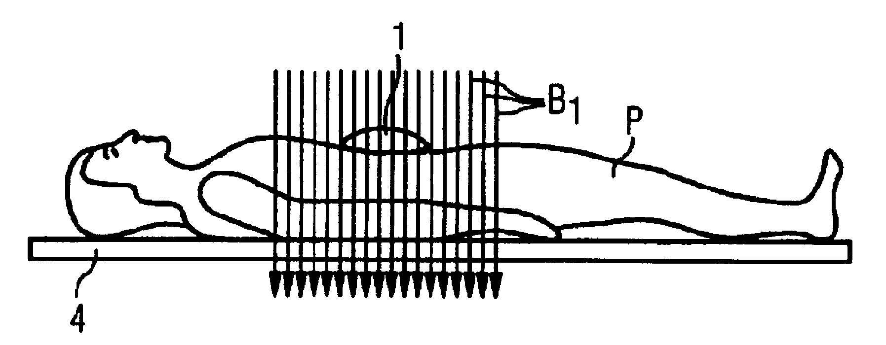
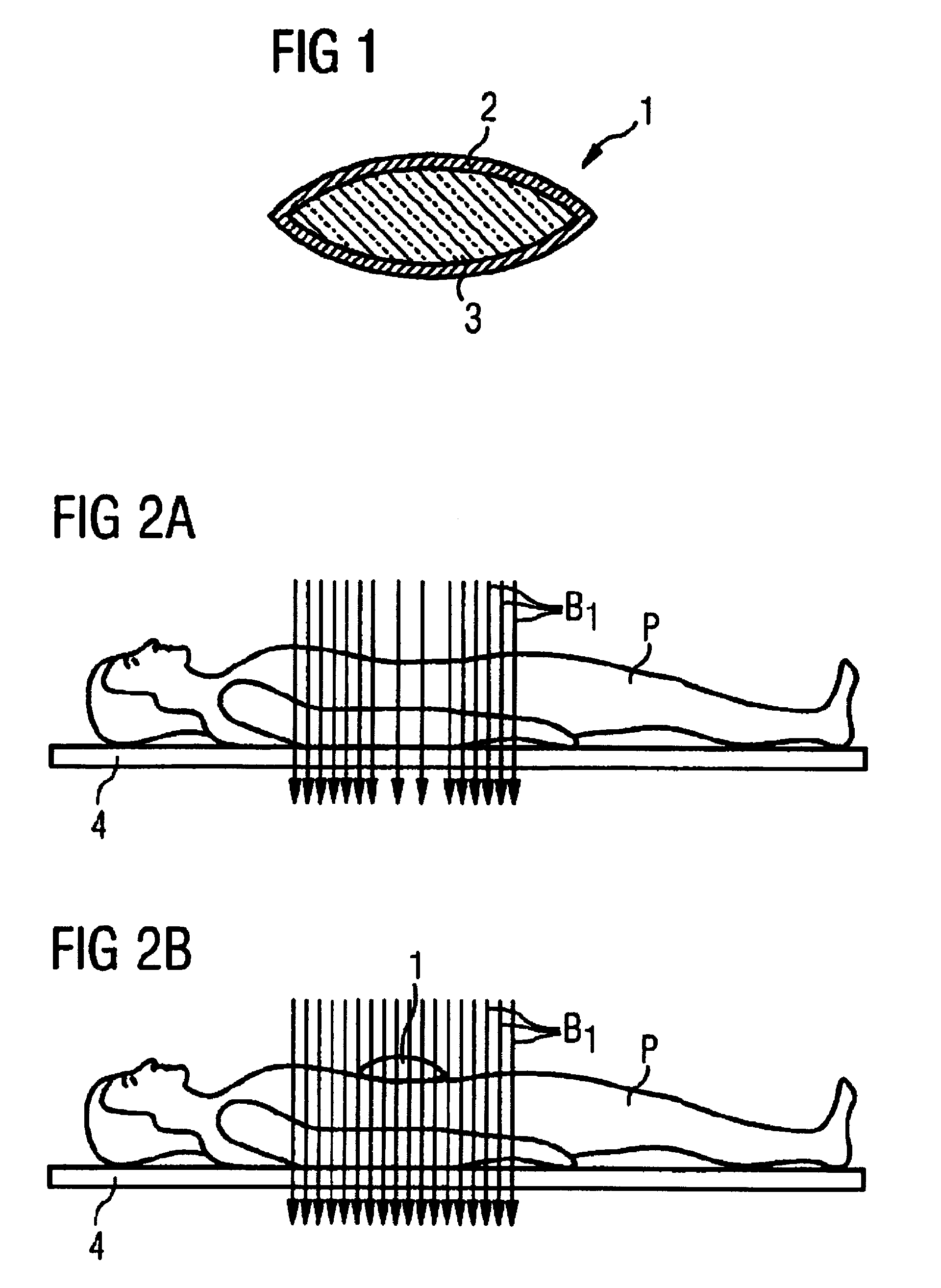
[0035]The dielectric element shown in FIG. 1 is a dielectric cushion 1 having an outer plastic film casing 2 and a filling 3 that contains a paramagnetic substance bound to particles of a cation exchanger. The plastic film 2 is a bio-friendly material which is relatively thin, but nevertheless sufficiently stable to prevent egress of the filling 3 contained therein. The plastic film 2 is preferably welded all round.

[0036]When in use, the dielectric cushion 1 can additionally be covered with a washable cushion cover which can be changed before using the dielectric cushion 1 on another patient. Advantageously the plastic film casing 2 can be disinfected using normal means.

[0037]In the specific example, the filling 3 is an aqueous sodium polyacrylate gel containing particles of the strongly acidic cation exchanger Dowex® 50 WX8 which is charged with Mn2+ ions. The cation exchanger used had the following characteristics: moisture content approx. 50 wt. %, ion exchange capacity: 4.8 meq / ...


PUM


Abstract

A dielectric element for positioning on an examination subject for locally influencing the B1 field distribution during magnetic resonance data acquisition contains a relaxation agent bound to mutually separated particles. The relaxation agent incorporates a paramagnetic substance. In a corresponding method for acquiring magnetic resonance data from an examination subject, such a dielectric element is positioned on the examination subject for locally influencing the B1 field distribution, by homogenizing the B1 field of a magnetic resonance apparatus.

Description

BACKGROUND OF THE INVENTION[0001]1. Field of the Invention[0002]The present invention relates to a dielectric element for positioning on an examination subject for locally influencing the B1 field distribution during magnetic resonance recording. The invention additionally relates to a method for acquiring magnetic resonance data from an examination subject, wherein such a dielectric element is positioned on the examination subject for locally influencing the B1 field distribution by homogenizing the B1 field of a magnetic resonance apparatus.[0003]2. Description of the Prior Art[0004]Magnetic resonance tomography is a technique that is widely used for obtaining images inside the body of an examination subject. In order to obtain an image with this modality, i.e. to produce a magnetic resonance recording of an examination subject, the patient's body or a body part thereof under examination must first be exposed to a highly homogeneous static basic magnetic field (usually termed the ...

Claims


Application Information

Patent Timeline
Patent Type & Authority Patents(United States)
IPC IPC(8): G01V3/00
CPCG01R33/28G01R33/5659
Inventor CANDIDUS, YVONNEFEIWEIER, THORSTENHUBER, JURGENSCHON, LOTHARSPECKNER, THORSTEN
Owner SIEMENS HEALTHCARE GMBH
Why Eureka
Try Eureka