Dielectric element and method for generating a magnetic resonance image therewith

a dielectric element and image technology, applied in the direction of magnetic variable regulation, instruments, applications, etc., can solve the problems of inhomogeneous penetration behavior of rf pulses, unwanted variations of received magnetic resonance signals, and inability to accurately detect the intensity of rf pulses, so as to reduce interference in magnetic resonance exposures

Inactive Publication Date: 2007-11-22
SIEMENS HEALTHCARE GMBH
View PDF3 Cites 3 Cited by
  • Summary
  • Abstract
  • Description
  • Claims
  • Application Information

AI Technical Summary

Benefits of technology

[0010] It is an object of the present invention to further develop a method for generation of magnetic resonance exposures using dielectric elements as well as a dielectric element, such that interferences in the magnetic resonance exposures are reduced or even entirely prevented in a simple manner by the positioned dielectric elements.
[0011] This object is achieved by a dielectric element and a method employing such a dielectric element wherein the dielectric element includes a relaxation agent that reduces the relaxation time of the dielectric element. Both the T1 relaxation time and the T2 relaxation time are reduced. The reduction can be up to 3 orders of magnitude, depending on the material of the dielectric element used and the relaxation agent. For example, the relaxation time of a conventional dielectric element, without the addition of the relaxation agent, would be on the order of 1 s. This would be lowered to less than 1 ms, for example, by the relaxation agent in accordance with the invention. The relaxation agent consequently ensures that the relaxation times of the diagnostically irrelevant dielectric element are shorter than the typical signal evolution times. This dielectric element thus is practically invisible in most applications, and interference-free data acquisition is possible. Since the inventive dielectric elements are not visible in the images, additional data acquisition time to prevent fold-over artifacts is not necessary. Typical imaging sequences thus can be unchanged in the inventive method and thus can be used without performance losses. Nevertheless, the desired homogenization effect of the B1 field is achieved in a simple manner.

Problems solved by technology

Spatial fluctuations in the field strength of the excited B1 field therefore lead to unwanted variations in the received magnetic resonance signal that can adulterate the measurement data.
In the presence of high magnetic field strengths—that are inevitable due to the necessary magnetic basic field B0 in a magnetic resonance tomography apparatus—the RF pulses disadvantageously exhibit an inhomogeneous penetration behavior in conductive and dielectric media such as, for example, tissue.
The material of the dielectric element, however, should not exhibit a conductivity that is too high because, due to the skin effect, this leads to high eddy currents, in particular in the surface region of the dielectric element, that in turn produce a shielding effect that weakens (attenuates) the dielectric focusing effect.
Unfortunately, the use of all of these “dielectric pillows” has the unwanted side effect that they are visible in the magnetic resonance exposures.
In addition to this, due to fold-over effects the dielectric element may not be imaged within the magnetic resonance exposure at the location at which it is actually positioned in real space.
Such oversampling methods, however, are quite time-consuming and therefore prolong the measurement time.

Method used


Image

  • Dielectric element and method for generating a magnetic resonance image therewith
  • Dielectric element and method for generating a magnetic resonance image therewith
  • Dielectric element and method for generating a magnetic resonance image therewith

Examples


Embodiment Construction

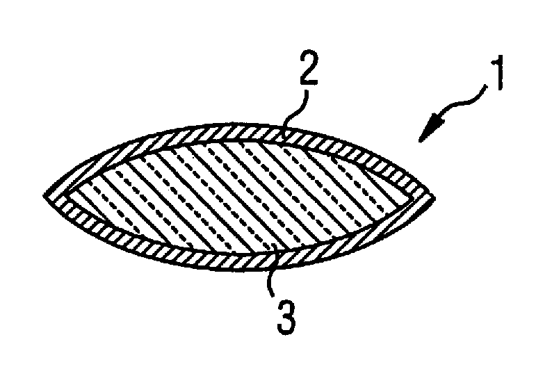
[0026] The dielectric element shown in FIG. 1 is a dielectric pillow 1 having an outer shell 2 made from plastic film and a filling 3 that contains a paramagnetic substance. The plastic film of the outer shell 2 is a biocompatible material that is relatively thin but nevertheless sufficiently stable to prevent escape of the filling 3 contained therein. The plastic film of the outer shell 2 is preferably fused all around.

[0027] In use, the dielectric pillow 1 can be covered with a washable pillowcase that can be changed before use of the dielectric pillow 1 with different patients. The plastic film of the outer shell 2 can advantageously by disinfected with typical means.

[0028] In the exemplary embodiment, the filling 3 is an aqueous sodium polyacrylate gel that incorporates a gadolinium complex as a paramagnetic substance. This special filling 3 has the advantage that it is completely safe for the patient, in addition to the desired properties of effecting homogenization of the tr...


PUM

PropertyMeasurementUnit
particle sizeaaaaaaaaaa
weight percentaaaaaaaaaa

Abstract

A dielectric element is formed of a dielectric material exhibiting a magnetic resonance relaxation time, with a relaxation agent incorporated in the dielectric material that reduces the relaxation time of the dielectric material. The dielectric element is adapted for placement on a subject while magnetic resonance data are acquired from the subject, and locally influences the B1 field distribution in the subject during the acquisition of magnetic resonance data.

Description

RELATED APPLICATION [0001] The present application is a divisional of Ser. No. 11 / 095,159, filed Mar. 31, 2005.BACKGROUND OF THE INVENTION [0002] 1. Field of the Invention [0003] The invention concerns a method for generation of magnetic resonance exposures (images) of an examination subject, in which a dielectric element is positioned on the examination subject for locally influencing the B1 field distribution. The invention also concerns such a dielectric element for positioning on an examination subject for local influencing the B1 field distribution during magnetic resonance data acquisition. [0004] 2. Description of the Prior Art [0005] Magnetic resonance tomography has become a widespread modality for acquisition of images of the inside of the body of a living examination subject. In order to acquire an image with this modality, i.e. to generate a magnetic resonance exposure of an examination subject, the body or a body part of the patient to be examined must initially be expo...

Claims


Application Information

Patent Timeline
Patent Type & Authority Applications(United States)
IPC IPC(8): A61B5/055A61B5/05G01R33/28G01R33/30G01R33/34G01R33/341
CPCG01R33/28Y10T29/49G01R33/5659G01R33/34
Inventor CANDIDUS, YVONNEFEIWEIER, THORSTENHORGER, WILHELMHUBER, JURGENLAZAR, RAZVANSCHMITT, MELANIESCHON, LOTHAR
Owner SIEMENS HEALTHCARE GMBH
Why Eureka
Try Eureka