
Automatic roller wringer

a technology of automatic wringing and rollers, which is applied in the direction of wringing machines, press rollers, washing apparatus, etc., can solve the problems of large use of electric power accumulated in batteries and loss of tim

Active Publication Date: 2008-10-14
SPRIMSOL LIMPIEZAS
View PDF15 Cites 8 Cited by
  • Summary
  • Abstract
  • Description
  • Claims
  • Application Information

AI Technical Summary

Benefits of technology

"The patent describes an automatic roller wringer for mops and similar cleaning devices. The purpose of the invention is to make it easier for people to wring mops by providing a machine that automatically removes water from the mop. The machine is supported by a heavy-duty bucket with wheels and incorporates a motor and battery to power it. It has rollers that rotate and move to remove water from the mop. The machine is controlled by a main switch and has a projection on the front face for easy operation. The technical effect of the invention is to provide a more efficient and effective solution for removing water from mops and similar cleaning devices."

Problems solved by technology

It has been shown that these parts which move like blades or the like, generating an approaching movement, do not definitively wring the mop or the like, as a result of which the user must actuate them on several occasions, on one hand leading to a loss of time, as well as a large use of electric power accumulated in the battery.

Method used


Image

  • Automatic roller wringer
  • Automatic roller wringer
  • Automatic roller wringer

Examples


Embodiment Construction

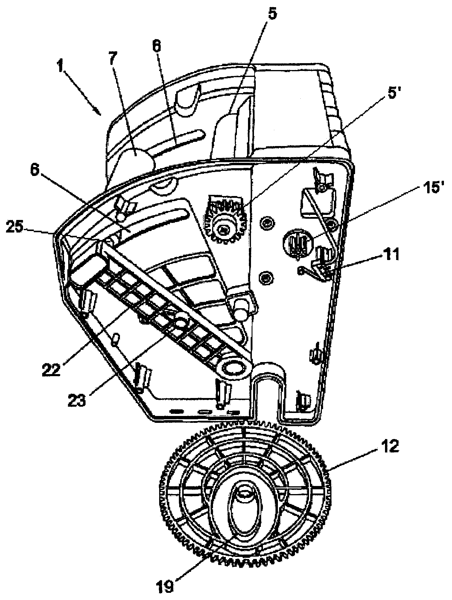
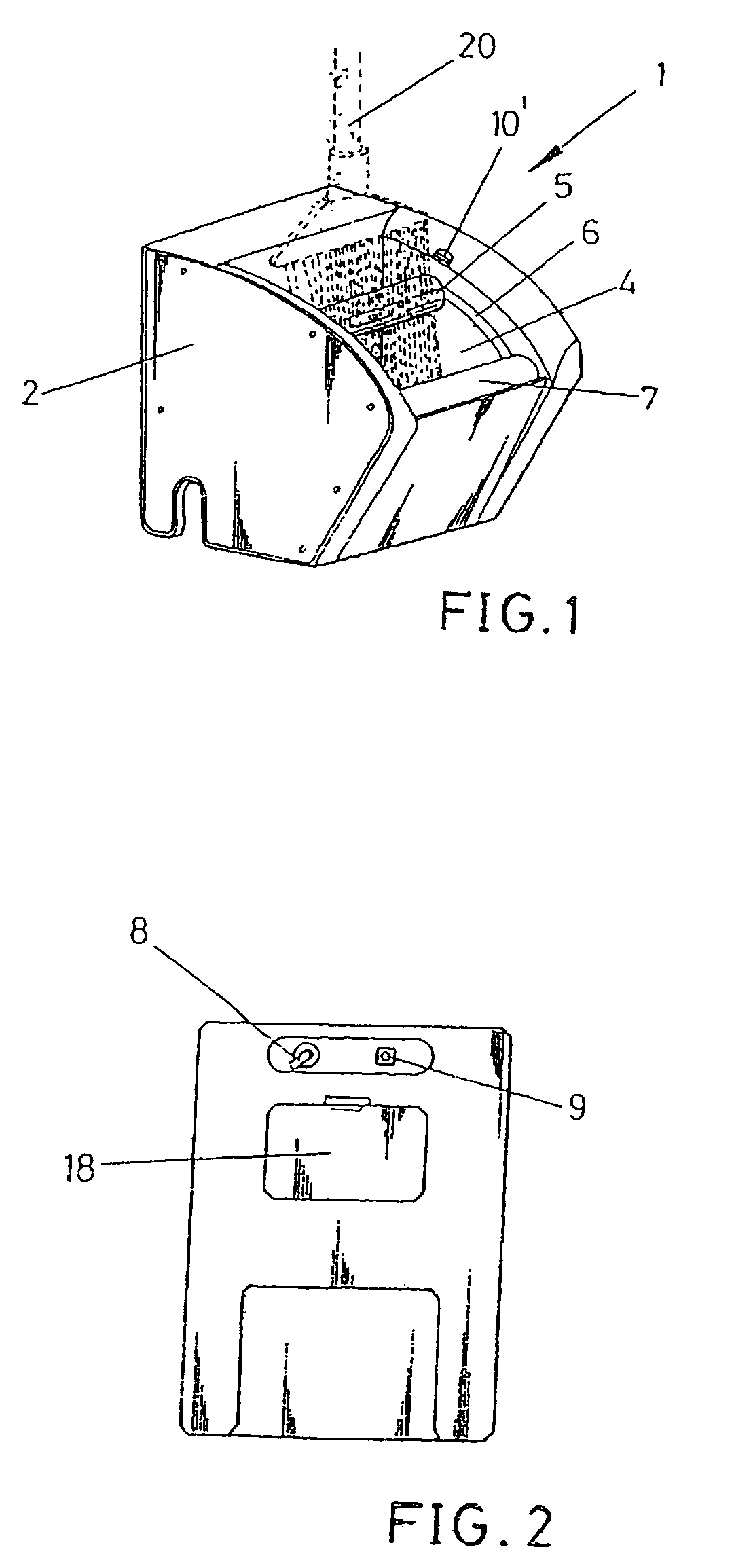
[0012]The present specification refers to an automatic roller wringer for mops and similar devices such as floor scrubbing devices, butts of the handle, and so on; the purpose of which is to facilitate the significant reduction of the effort made by those persons who perform the job of wringing the mop for cleaning floors, or of any similar element, automatically performing the wringing of the mop or the like located on the lower part of the mop handle.

[0013]The automatic roller wringer for mops and the like proposed by the invention is a novelty element itself, providing within its context all those features defined as solutions to the evident drawbacks in this matter.

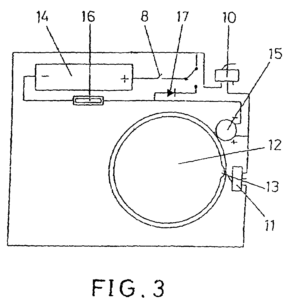
[0014]More specifically, the automatic roller wringer for mops and the like object of the invention is constituted of a heavy-duty bucket provided with wheels which facilitate transporting it, on which bucket the automatic roller wringer for mops and the like is supported, internally incorporating different mechanisms...


PUM

PropertyMeasurementUnit
areaaaaaaaaaaa
pressureaaaaaaaaaa
lengthaaaaaaaaaa

Abstract

An automatic roller wringer for mops and the like, consisting of the incorporation of the main gears inside the casing, one of the gears being provided with a projection for the stop, the main gears being asymmetrically assembled on either side, engaging with the fixed roller, each one of the main gears being provided with an eccentric guide on the inner part through which the pivots of the movable roller pass until the latter is in a position adjacent to the fixed roller, which upwardly rotates, the arms supporting the pivots of the arm of the movable roller being provided with a spring on each one.

Description

CROSS-REFERENCE TO RELATED APPLICATIONS[0001]This application is a continuation-in-part of U.S. application Ser. No. 10 / 758,526, filed Jan. 16, 2004, now abandoned.STATEMENT REGARDING FEDERALLY SPONSORED-RESEARCH OR DEVELOPMENT[0002]None.INCORPORATION BY REFERENCE OF MATERIAL SUBMITTED ON A COMPACT DISC[0003]None.FIELD OF THE INVENTION[0004]This invention is applicable within the industry dedicated to the manufacture of domestic and industrial cleaning apparatuses, especially within the industry dedicated to the manufacture of automatic wringers or similar devices.BACKGROUND OF THE INVENTION[0005]The applicant knows of the existence of several devices or elements applicable as wringers which are provided with mechanical actuation elements, operated by the user or users of these elements, configured from clamps, rollers or coupling elements which, directly operated by the user by means of a crank or other actuator, achieve removing water contained by the mop.[0006]The applicant likew...

Claims


Application Information

Patent Timeline
Patent Type & Authority Patents(United States)
IPC IPC(8): A47L13/60
CPCA47L13/60
Inventor RAMIREZ MORENO, JOSE DAMIAN
Owner SPRIMSOL LIMPIEZAS
Learn More