Light scanning apparatus and method to prevent damage to an oscillation mirror in an abnormal control condition via a detection signal outputted to a controller even though the source still emits light

a detection signal and control apparatus technology, applied in the field of light, can solve the problems of destroying the oscillation mirror, not being able to enter amplitude control, and light detecting sensors failing to output detection signals indicative, etc., to prevent the destruction of the oscillation mirror

Inactive Publication Date: 2008-10-14
SEIKO EPSON CORP
View PDF14 Cites 19 Cited by
  • Summary
  • Abstract
  • Description
  • Claims
  • Application Information

AI Technical Summary

Benefits of technology

[0011]The conventional apparatus comprises a controller for the purpose of controlling the amplitude of the oscillation mirror which may be a resonance-type actuator or the like. The controller is configured so as to control the drive control variable such as a drive current based on the signal which is output from the light detecting sensor. The amplitude of the oscillation mirror is adjusted by means of control of the drive control variable. When the controller feeds an improper drive signal to the oscillation mirror under the influence of a noise or disturbance therefore, the angle of amplitude of the oscillation mirror could significantly change. Particularly when a noise or other influential factor acts to additionally vibrate the oscillation mirror, the oscillation mirror could oscillate beyond its destruction limit angle and get destroyed. Thus, the noise or other influential factor may make the apparatus come into the abnormal control condition, so that the oscillation mirror is crashed. Hence, it is very important to prevent without fail an oscillation mirror from vibrating up to its destruction limit angle in the case of a light scanning apparatus in which the oscillation mirror makes a light beam scan.
[0012]An object of the invention is to prevent destruction of an oscillation mirror in a light scanning apparatus in which a detector such as a light detecting sensor detects a light beam which is made scan by the oscillation mirror of the resonance-type and the oscillation mirror is controlled based on the detection result.

Problems solved by technology

Hence, when there is a trouble with the light source or the light detecting sensor, an influence due to a noise, etc., the light detecting sensor may fail to output the detection signal indicative of the light beam even though the angle of amplitude of the oscillation mirror is equal to or larger than an angle which corresponds to the location at which the light detecting sensor is disposed.
On that occasion, it is not possible to enter amplitude control based on an output signal from the light detecting sensor, which could further vibrate and destroy the oscillation mirror.
Thus the abnormal controlling in the apparatus may cause the oscillation mirror to crash.
The reason is that the light detecting sensor for some reason may fail to properly output a detection signal indicative of a light beam.
Particularly when a noise or other influential factor acts to additionally vibrate the oscillation mirror, the oscillation mirror could oscillate beyond its destruction limit angle and get destroyed.
Thus, the noise or other influential factor may make the apparatus come into the abnormal control condition, so that the oscillation mirror is crashed.

Method used


Image

  • Light scanning apparatus and method to prevent damage to an oscillation mirror in an abnormal control condition via a detection signal outputted to a controller even though the source still emits light
  • Light scanning apparatus and method to prevent damage to an oscillation mirror in an abnormal control condition via a detection signal outputted to a controller even though the source still emits light
  • Light scanning apparatus and method to prevent damage to an oscillation mirror in an abnormal control condition via a detection signal outputted to a controller even though the source still emits light

Examples


first embodiment

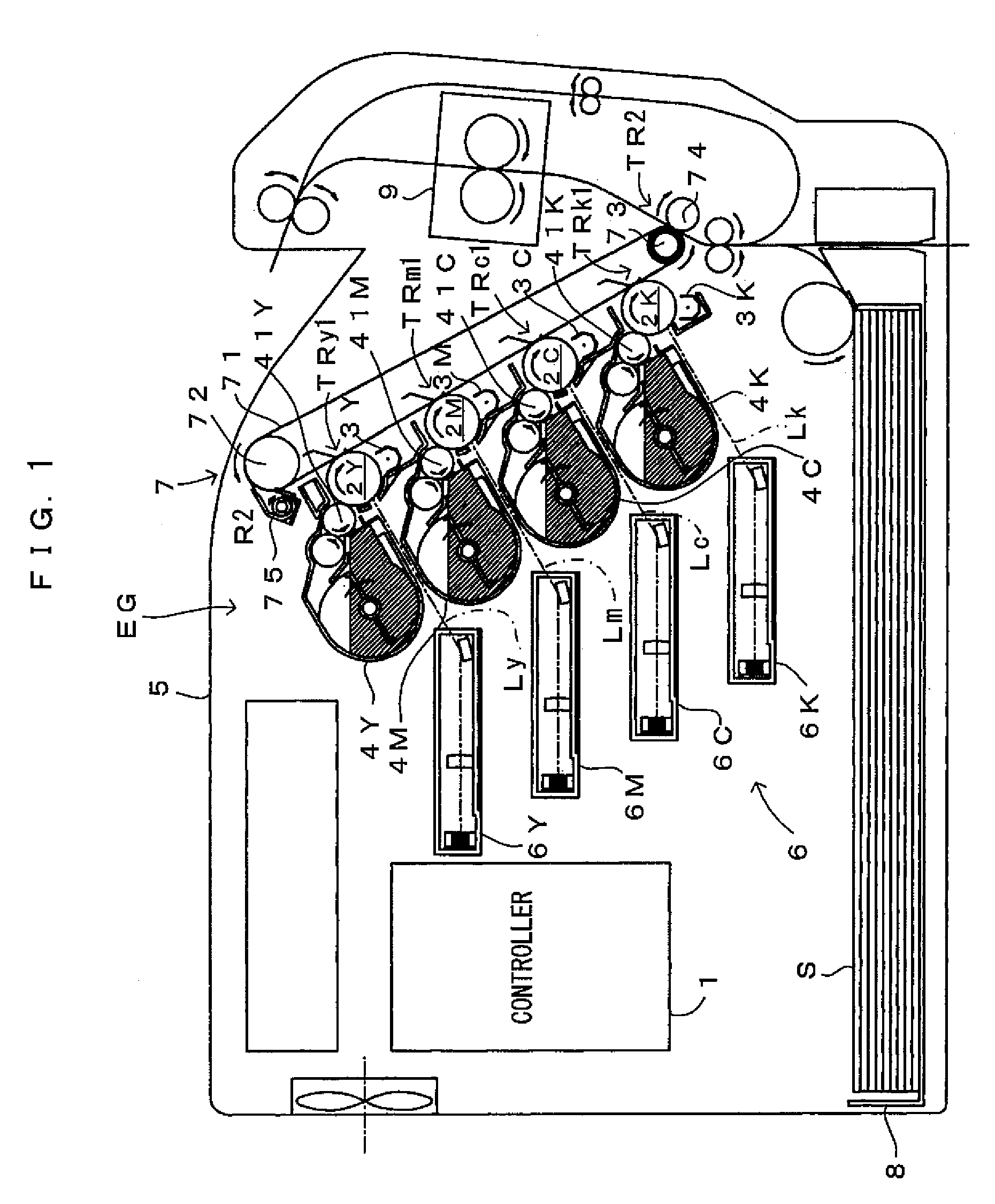
[0029]FIG. 1 is a diagram showing an image forming apparatus according to a first embodiment of the invention. This image forming apparatus is a so-called tandem color printer wherein photosensitive members 2Y, 2M, 2C, 2K for four colors of yellow Y, magenta M, cyan C and black K, as latent image carriers, are juxtaposed in an apparatus body 5. The apparatus is adapted to form a full-color image by superimposing toner images on the individual photosensitive members 2Y, 2M, 2C, 2K, or to form a monochromatic image using only the toner image of black (K). The image forming apparatus operates as follows. When an external apparatus such as a host computer applies an image forming command to a controller 1 in response to a request from a user wanting to form an image, the controller 1 sends image signals, a reference signal, control signals and the like. In response to the signals from the controller 1, individual parts of an engine section EG operate to form the image corresponding to t...

second embodiment

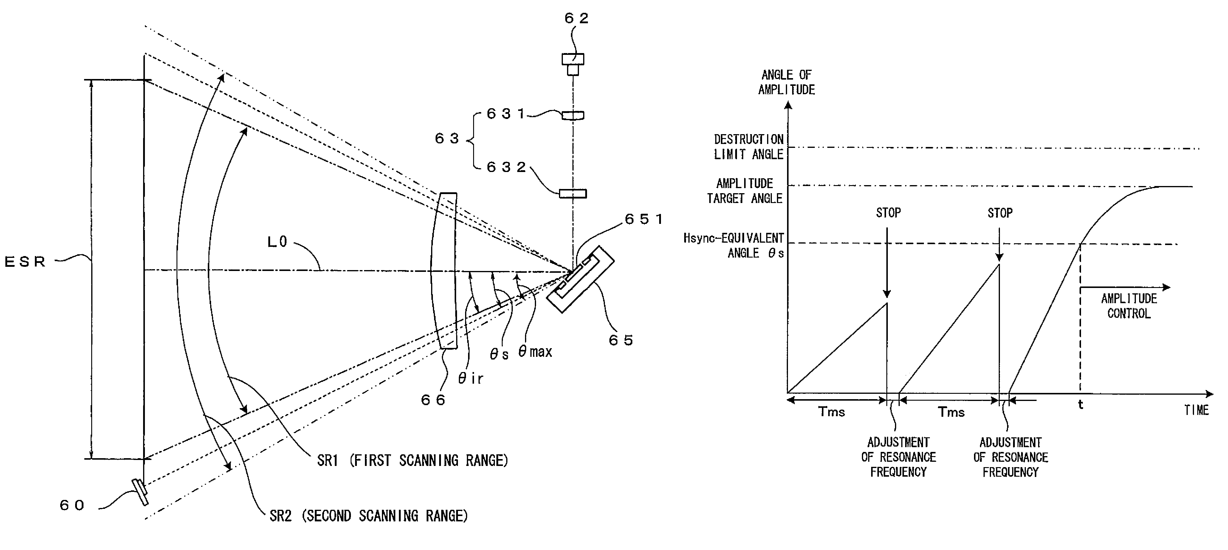
[0059]While amplitude control is performed normally, the output timing gap Tnp between the first and the second detection signals is approximately constant and the maximum angle of amplitude θmax is at the amplitude target value. However, if the mirror drive controller 111 feeds an improper mirror drive signal to the operating section 652 of the deflector 65 under the influence of a noise or disturbance, the angle of amplitude of the deflector 65 could significantly change. The influence of a noise or the like in particular may vibrate the deflector 65 further. Noting this, the second embodiment requires monitoring a change of the amplitude of the deflector 65, and upon confirmation of an abnormal operation (which is an amplifying operation that the maximum angle of amplitude θmax grows toward the destruction limit angle), stopping driving of the deflector 65. This will now be described in detail with reference to FIGS. 9, 10A and 10B. The basic structure of the apparatus according ...

third embodiment

[0066]FIG. 11 is a flow chart which shows an operation according to the third embodiment of the light scanning apparatus of the invention. FIG. 12 is a drawing of the operation according to the third embodiment. A major difference of the third embodiment from the second embodiment (FIG. 9) is at the criterion regarding the abnormal operation. In the third embodiment, when the maximum angle of amplitude θmax has exceeded a predetermined angle of amplitude for a pre-set number of times N (which is a natural number equal to or larger than 2) in a row, the abnormal operation is confirmed. The structure is otherwise the same basically. The third embodiment will now be described with reference to FIGS. 11 and 12.

[0067]In this embodiment, upon confirmation of the start of amplitude control (Step S31), the count N is reset to zero (Step S32). The measuring unit 113 then calculates a output timing gap Tnp between two consecutive detection signals Hsync which are output as the reciprocal ligh...


PUM


Abstract

A light scanning apparatus makes a light beam scan along a main scanning direction on an effective scanning region having a predetermined width. A deflector includes an oscillation mirror which deflects the light beam and makes the light beam scan a second scanning range which contains but extends beyond a first scanning range corresponding to the effective scanning region A detector detects the scanning light beam which moves through a position outside the first scanning range but within the second scanning range, and outputs a detection signal A controller drives the oscillation mirror based on the detection signal and accordingly adjusts the amplitude of the oscillation mirror, and stops driving the oscillation mirror when the detection signal is not outputted from the detector even though a light source is turned on to emit the light beam.

Description

CROSS REFERENCE TO RELATED APPLICATION[0001]The disclosure of Japanese Patent Applications enumerated below including specification, drawings and claims is incorporated herein by reference in its entirety:[0002]No. 2005-224945 filed Aug. 3, 2005; and[0003]No. 2005-226206 filed Aug. 4, 2005.BACKGROUND[0004]1. Technical Field[0005]The present invention relates to a light scanning apparatus which deflects a light beam using an oscillation mirror and makes the light beam scan in a main scanning direction, and also to a method of controlling such an apparatus. The present invention relates to an image forming apparatus having such a light scanning apparatus, too.[0006]2. Related Art[0007]It is conventionally proposed that a light scanning apparatus has a resonance-type oscillation mirror formed using a micromachining technique as a deflector. Such an oscillation mirror has a deflecting mirror surface which is capable of oscillating about a drive shaft. As the deflecting mirror surface os...

Claims


Application Information

Patent Timeline
Patent Type & Authority Patents(United States)
IPC IPC(8): G02B26/08H01J3/14
CPCG02B26/105G02B27/0031Y10S359/90
Inventor GOMI, AKIHIRONOMURA, YUJIROIKUMA, KEN
Owner SEIKO EPSON CORP
Why Eureka
Try Eureka