Optical lens system for taking image
a technology of optical lens and image, applied in the field of optical lens system for taking image, can solve the problems of poor uniformity, difficult to insert the three lens elements into the space of the optical system, and less space available for the optical system, so as to reduce the probability of shading, improve the photosensitivity of the sensor, and improve the effect of image quality
- Summary
- Abstract
- Description
- Claims
- Application Information
AI Technical Summary
Benefits of technology
Problems solved by technology
Method used
Image

Examples
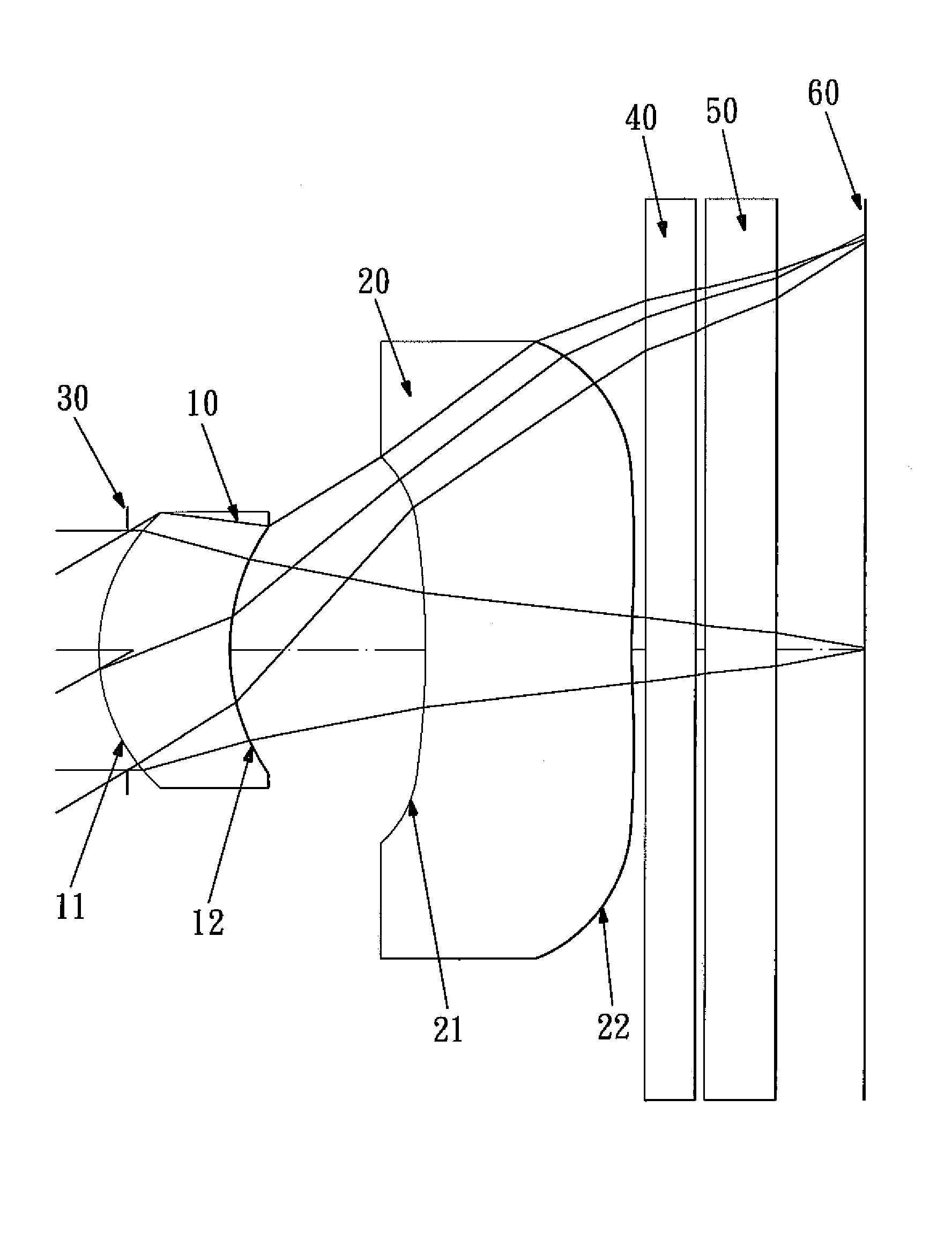
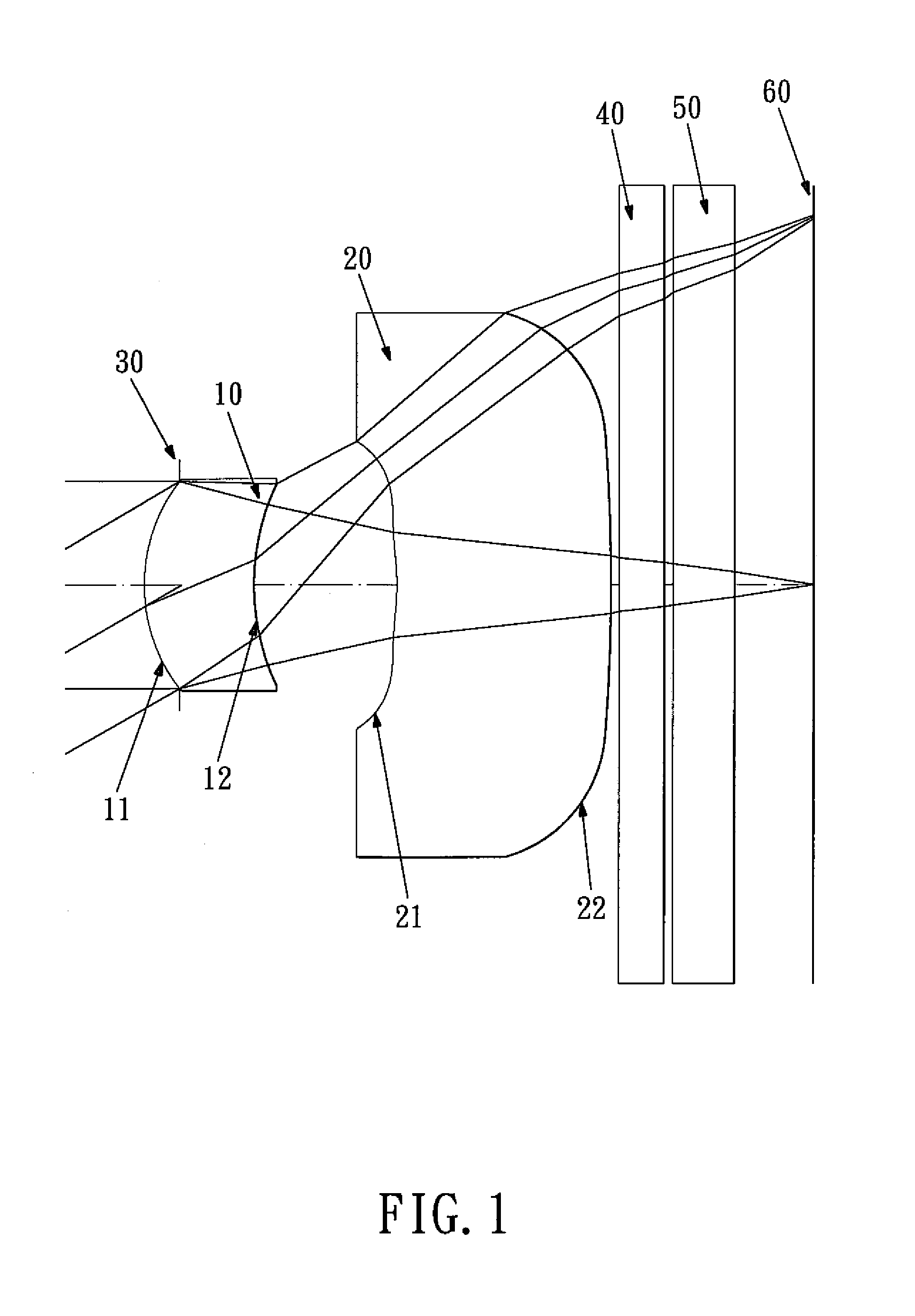
first embodiment
[0060]In the present optical lens system for taking image, the focal length of the first lens element is f1, the focal length of the second lens element is f2, the focal length of the optical lens system for taking image is f, the Entrance Pupil Diameter is EPD, and they satisfy the relations:
f / f1=1.11
f / f2=−0.24
f / EPD=2.85.
[0061]In the first embodiment of the present optical lens system for taking image, the radius of curvature of the object-side surface of the first lens element is RI, the radius of curvature of the image-side surface of the first lens element is R2, the radius of curvature of the object-side surface of the second lens element is R3, the radius of curvature of the image-side surface of the second lens element is R4, and they satisfy the relations:
R1 / R2=0.52
R3 / R4=−0.24
[0062]In the first embodiment of the present optical lens system for taking image, the refractive index of the first lens element is N1, and it satisfies the relation:
N1=1.543
[0063]In the first embodime...
second embodiment
[0078]In the present optical lens system for taking image, the focal length of the first lens element is f1, the focal length of the second lens element is f2, the focal length of the optical lens system for taking image is f, the Entrance Pupil Diameter is EPD, and they satisfy the relations:
f / f1=1.07
f / f2=−0.21
f / EPD=2.87.
[0079]In the second embodiment of the present optical lens system for taking image, the radius of curvature of the object-side surface of the first lens element is R1, the radius of curvature of the image-side surface of the first lens element is R2, the radius of curvature of the object-side surface of the second lens element is R3, the radius of curvature of the image-side surface of the second lens element is R4, and they satisfy the relations:
R1 / R2=0.59
R3 / R4=−2.24.
[0080]In the second embodiment of the present optical lens system for taking image, the refractive index of the first lens element is N1, and it satisfies the relation:
N1=1.543
[0081]In the second embo...
third embodiment
[0096]In the present optical lens system for taking image, the focal length of the first lens element is f1, the focal length of the second lens element is f2, the focal length of the optical lens system for taking image is f, the Entrance Pupil Diameter is EPD, and they satisfy the relations:
f / f1=1.12
f / f2=−0.28
f / EPD=2.85.
[0097]In the third embodiment of the present optical lens system for taking image, the radius of curvature of the object-side surface of the first lens element is R1, the radius of curvature of the image-side surface of the first lens element is R2, the radius of curvature of the object-side surface of the second lens element is R3, the radius of curvature of the image-side surface of the second lens element is R4, and they satisfy the relations:
R1 / R2=0.51
R3 / R4=−0.37.
[0098]In the third embodiment of the present optical lens system for taking image, the refractive index of the first lens element is N1, and it satisfies the relation:
PUM
 Abstract
Description
Claims
Application Information
 - R&D
- Intellectual Property
- Life Sciences
- Materials
- Tech Scout
- Unparalleled Data Quality
- Higher Quality Content
- 60% Fewer Hallucinations
Browse by: Latest US Patents, China's latest patents, Technical Efficacy Thesaurus, Application Domain, Technology Topic, Popular Technical Reports.
© 2025 PatSnap. All rights reserved.Legal|Privacy policy|Modern Slavery Act Transparency Statement|Sitemap|About US| Contact US: help@patsnap.com