
Scattered pilot and filtering for channel estimation

a pilot and channel estimation technology, applied in the field of scattering pilots and filtering for channel estimation, can solve the problems of only suitable patterns, difficulty in completing minimum overhead, and needing a relatively high density of pilots and a completed interpolator, so as to improve channel estimation, improve network performance, and increase the value of such services

Active Publication Date: 2008-10-14
APPLE INC
View PDF7 Cites 115 Cited by
  • Summary
  • Abstract
  • Description
  • Claims
  • Application Information

AI Technical Summary

Benefits of technology

[0025]for the or each antenna, obtaining historical data regarding channel conditions, and inserting scattered pilot symbols in a scattered pattern dependent upon said historical data. This enables the pilot symbol pattern to be dynamically varied according to the prevalent channel conditions thus improving channel estimation over time.
[0029]According to a third aspect of the invention there is provided an OFDM transmitter comprising at least one transmit antenna capable of receiving historical data regarding channel conditions, and inserting scattered pilot symbols in a scattered pattern dependent upon said historical data. This improves the accuracy of the channel estimation, since the scattered pilot parameters are selected according to prevalent channel conditions, rather than being preset and / or set to an “average” of expected channel conditions.
[0035]Further aspects of the invention include an improved data transmission service in which pilot symbols are inserted in a pattern dependent upon historical data regarding channel conditions and / or including use of an adaptive channel estimation filter whose size and shape can be selected or varied to optimise channel estimation, according to historical data regarding channel conditions. As the advantages of the invention can enable a better network which provides improved channel estimation, consequently a data transmission service over the network can show a corresponding improvement and the value of such services can increase. Such increased value over the life of the system could prove far greater than the sales value of the equipment.

Problems solved by technology

However, it needs a relatively high density of pilots and a completed interpolator.
To interpolate and reconstruct the channel response function from the limited pilots to achieve reliable channel estimation with the minimum overhead is a challenging task.
However, such a pilot pattern is only suitable for channels that vary very slowly with time.
However, such a pilot pattern is only suitable for channels that vary slowly with frequency.
However, because pilot symbols constitute an overhead, a tighter pilot pattern comes at the expense of the useful transmitted data rate.
This increases the overhead in the signal.
The problem of minimising the number of pilot symbols while maximising the accuracy of the interpolation is also particularly cumbersome in Multiple-Input Multiple-Output (MIMO) OFDM systems.
This increases the temporal separation of the pilot symbols for each transmitter, reducing the accuracy of the interpolation used to estimate the channel response.
In practice it is very likely that the receiver will be in an environment that does not match this average situation in which case, the accuracy of the channel estimation is limited by these “average” settings, which may adversely affect downlink throughput to the receiver.

Method used


Image

  • Scattered pilot and filtering for channel estimation
  • Scattered pilot and filtering for channel estimation
  • Scattered pilot and filtering for channel estimation

Examples


Embodiment Construction

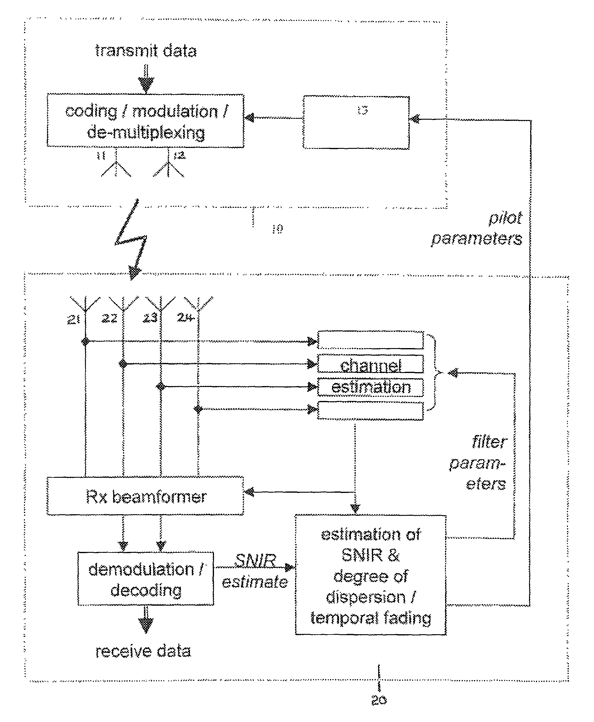
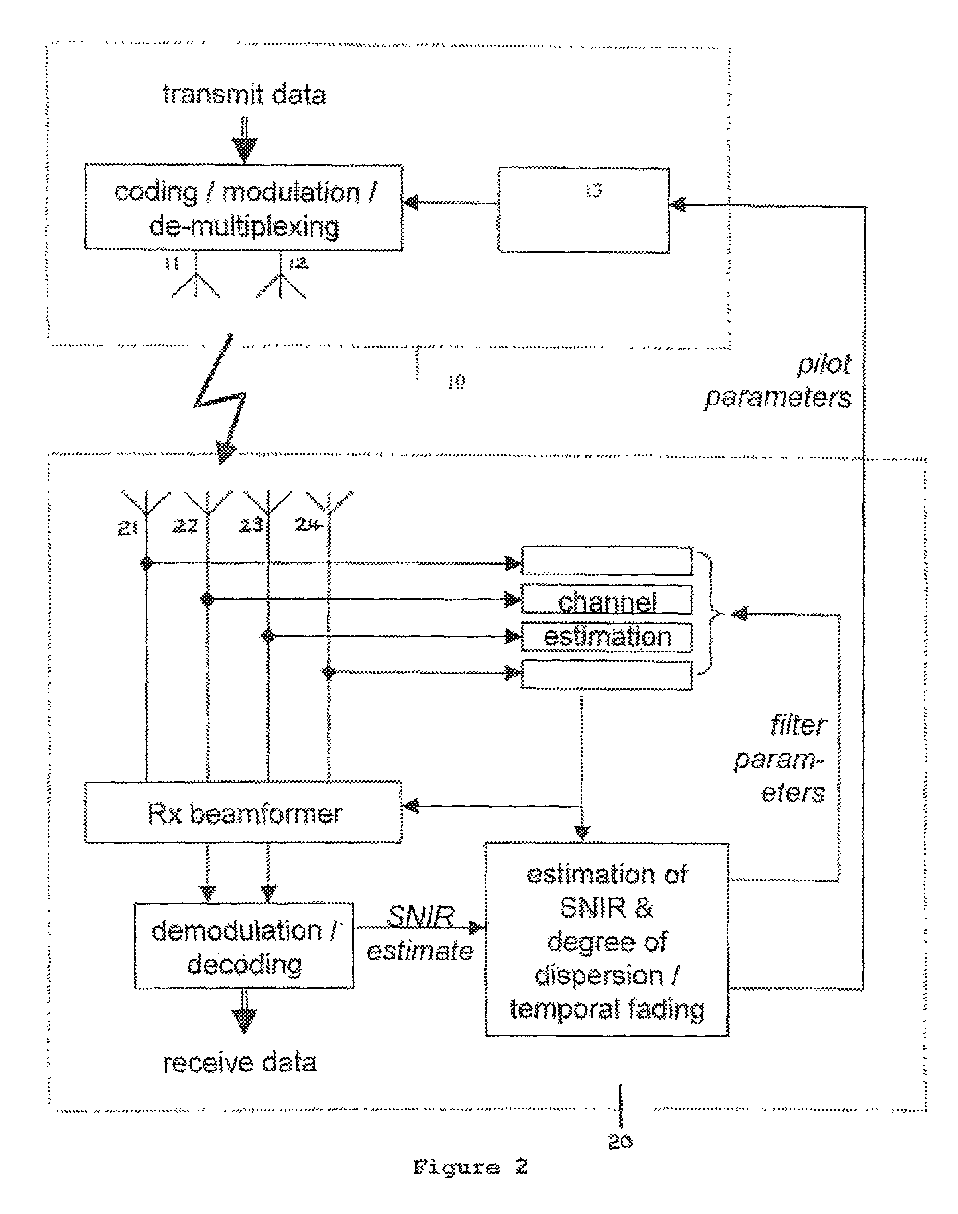
[0044]The system illustrated in FIG. 2 shows the downlink of a MIMO-OFDM system, wherein the base station 10 is transmitting data to a particular User Equipment (UE) 20. By way of example, a 2:4 MIMO scheme is shown—i.e. there are two transmit antennas 11, 12 at the base station 10, and four receive antennas 21, 22, 23, 24 at the UE 20. Data to be transmitted to the UE 20 is first coded and modulated, and then de-multiplexed onto the two transmit antennas 11, 12. This de-multiplexing stage can also be performed before the coding and modulation, if it is desirable to use, for example, a different modulation and coding scheme (MCS) on each transmitter.

[0045]In addition to the data, a scattered pilot is inserted by pilot insertion module 13, as shown in FIG. 2. This essentially involves the transmission of known pilot symbols at regular points in the OFDM frame, in both time and frequency, in order to allow the UE to determine the channel responses. A possible arrangement is given in F...


PUM


Abstract

Methods of improving channel estimation are described, in which pilot symbols are inserted into orthogonal frequency division multiplexing (OFDM) frames at an OFDM transmitter having at least one transmitting antenna, wherein for the or each antenna, historical data regarding channel conditions is obtained so that the scattered pilot symbols are inserted in a scattered pattern dependent upon said historical data. Alternatively, or in addition, an adaptive channel estimation filter is used whose parameters are selected according to analysis of historical data regarding channel conditions.

Description

FIELD OF THE INVENTION[0001]This invention relates to an orthogonal frequency division multiplexing (OFDM) communication systems, and more particularly to a more efficient use of pilot symbols within such systems.BACKGROUND TO THE INVENTION[0002]Multiple Input Multiple Output-Orthogonal Frequency Division Multiplexing (MIMO-OFDM) is a highly spectral efficient technology used to transmit high-speed data through radio channels with fast fading both in frequency and in time.[0003]In wireless communication systems that employ OFDM, a transmitter transmits data to a receiver using many sub-carriers in parallel. The frequencies of the sub-carriers are orthogonal. Transmitting the data in parallel allows the symbols containing the data to be of longer duration, which mitigates the effects of multi-path fading in particular dispersion. The orthogonality of the frequencies allows the sub-carriers to be tightly spaced, while minimising inter-carrier interference. At the transmitter, the data...

Claims


Application Information

Patent Timeline
IPC IPC(8): H04J11/00
CPCH04L5/0058H04L5/006H04L25/0222H04L25/0232H04L5/0007H04L5/0023H04L5/0048H04L25/0226
Inventor WILSON, KEITH SBEVAN, D. DAMIAN N.
Owner APPLE INC
Learn More