Reception apparatus and method, and channel response measurement apparatus for receiving an orthogonal frequency divisional multiplexing signal

Inactive Publication Date: 2008-10-14
SOCIONEXT INC
View PDF10 Cites 14 Cited by
  • Summary
  • Abstract
  • Description
  • Claims
  • Application Information

AI Technical Summary

Benefits of technology

[0057]According to the present invention, channel responses varying at high speed can be estimated accurately without the necessity of increasing the circuit size so greatly. This enables appropriate equalization of a received signal, and thus greatly improves the demodulation performance of the OFDM signal and the like even in the reception environment in which fading occurs vigorously, such as that surrounding mobile units.

Problems solved by technology

In particular, in a reception environment where the channel responses vary at high speed, the conventional time axis interpolation using zero-order interpolation or linear interpolation will cause a large error between the estimated channel responses and the actual channel responses.
With such an error, it fails to appropriately remove the influence of the channel on the received signal, and this results in degrading the demodulation performance.
In the linear interpolation, the error can be made smaller compared with that in the zero-order interpolation, but yet an error of some degree occurs in estimating channel responses varying at high speed.
However, as the number of taps of the filter increases, the memory capacity must be larger, and this increases the circuit size.
In addition, the FIR filter-using time axis interpolation causes a delay corresponding to the number of taps of the filter.
Therefore, as the number of taps increase, the capacity of the delay memory must be larger, and this increases the circuit size.

Method used


Image

  • Reception apparatus and method, and channel response measurement apparatus for receiving an orthogonal frequency divisional multiplexing signal
  • Reception apparatus and method, and channel response measurement apparatus for receiving an orthogonal frequency divisional multiplexing signal
  • Reception apparatus and method, and channel response measurement apparatus for receiving an orthogonal frequency divisional multiplexing signal

Examples


embodiment 1

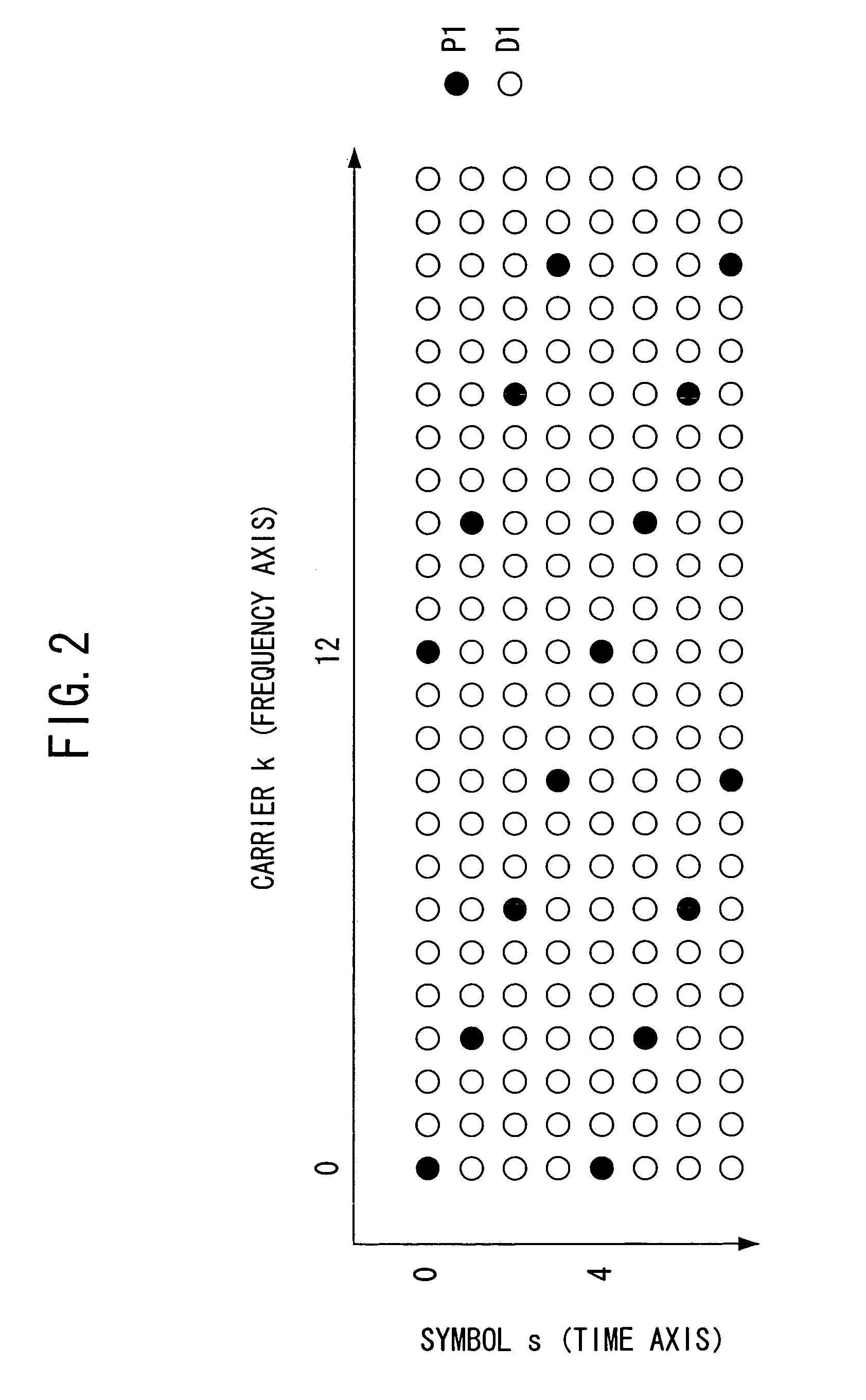
[0083]In Embodiment 1, a reception apparatus will be described, which determines channel responses corresponding to first, second and third pilot signals sequentially transmitted in each of pilot carriers among carriers constituting a received OFDM signal, and estimates channel responses at symbols between the second and third pilot signals of the carrier based on the determined channel responses.

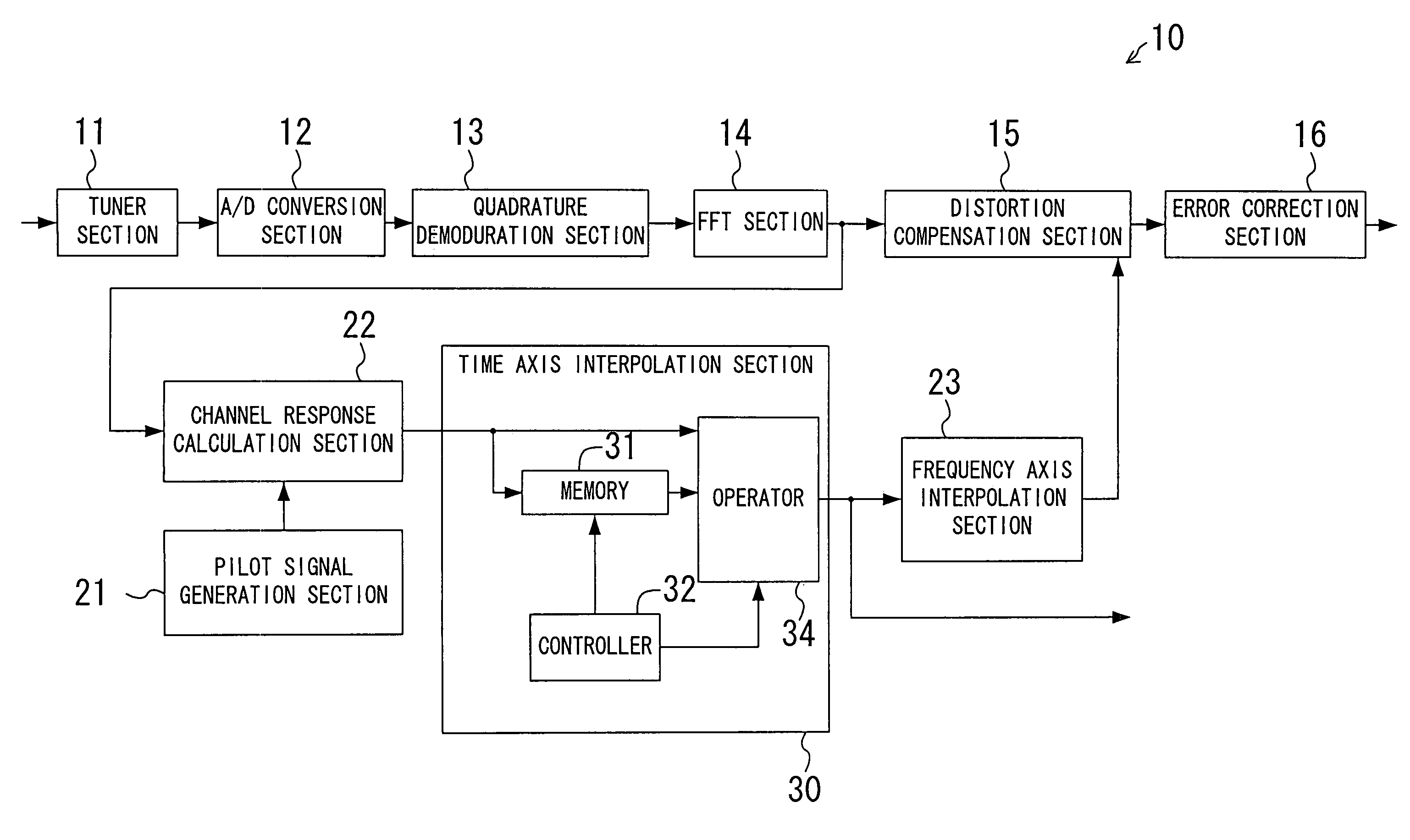
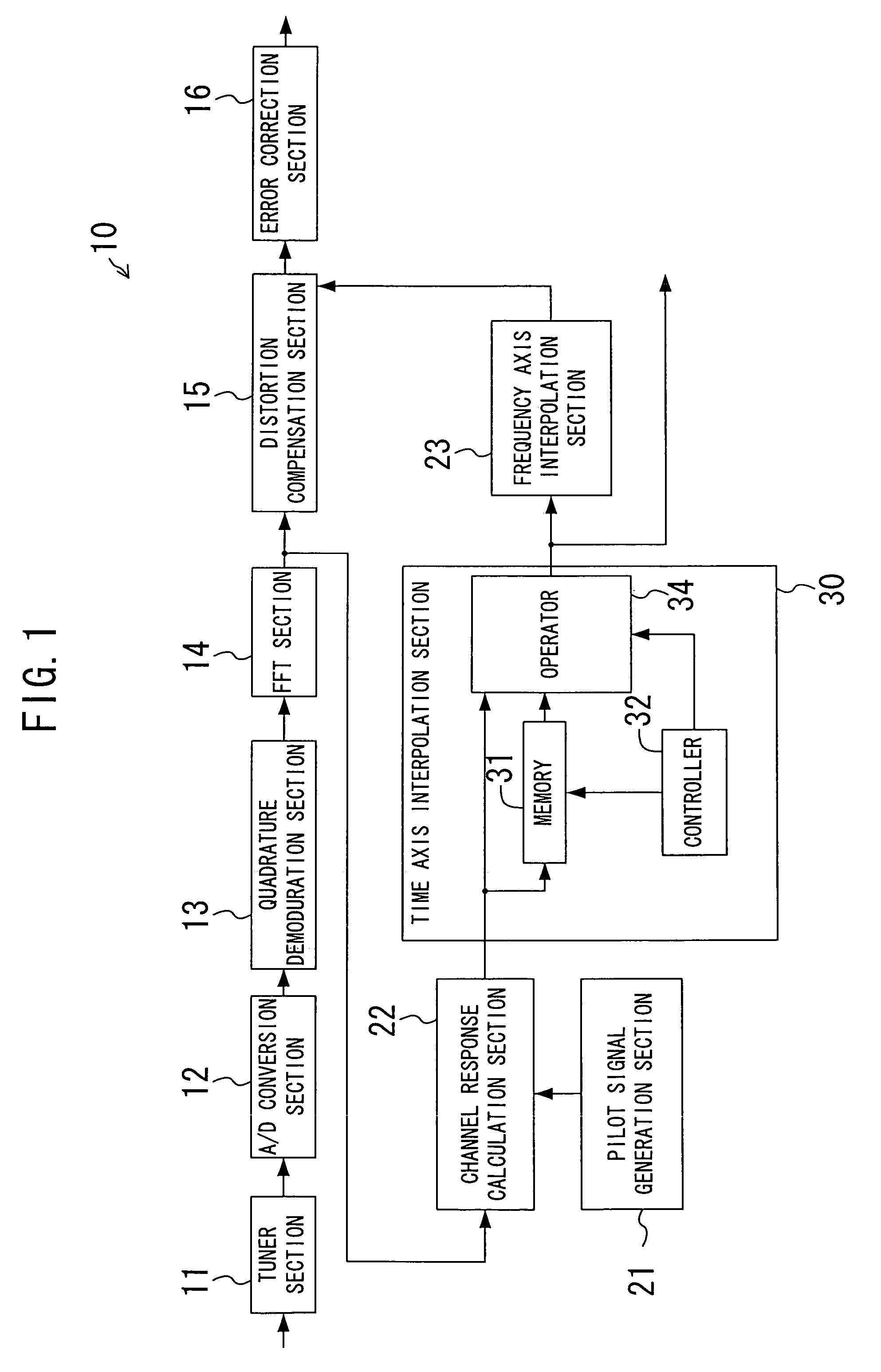
[0084]FIG. 1 is a block diagram showing a configuration of a reception apparatus of Embodiment 1 of the present invention. The reception apparatus of FIG. 1 includes a tuner section 11, an A / D conversion section 12, a quadrature demodulation section 13, a FFT section 14 as the Fourier transform section, a distortion compensation section 15, an error correction section 16, a pilot signal generation section 21, a channel response calculation section 22, a frequency axis interpolation section 23 and a time axis interpolation section 30. The time axis interpolation section 30 includes a memory ...

first alteration to embodiment 1

[0180]In the reception apparatus of FIG. 1, in determination of channel responses for signals between the second and third pilot signals, linear operation was executed for the linear-extrapolated channel responses Ha and the linear interpolated channel responses Hb using the predefined coefficients u1, u2 and u3 as in the expression (8) or (10). In the following alteration, the values of the coefficients u1, u2 and u3 are be changed according to the receiving state.

[0181]FIG. 13 is a block diagram of a configuration of a time axis interpolation section 130 of a reception apparatus of a first alteration to Embodiment 1. The reception apparatus of this alteration is different from the reception apparatus of FIG. 1 in that the time axis interpolation section 130 is provided in place of the time axis interpolation section 30. The other components are the same as those described with reference to FIG. 1 and thus denoted by the same reference numerals. Description of these components is t...

second alteration to embodiment 1

[0197]In this alteration, described will be the case of controlling the proportion of contribution of the linear-extrapolated channel response according to the extent of the influence of interference due to fading, in determination of a channel response using both linear extrapolation and linear interpolation.

[0198]FIG. 15 is a block diagram showing a configuration of a time axis interpolation section 230 of a reception apparatus of the second alteration to Embodiment 1. The reception apparatus of this alteration is different from the reception apparatus of FIG. 1 in that the time axis interpolation section 230 is provided in place of the time axis interpolation section 30 in FIG. 1. The time axis interpolation section 230 includes a channel response determination portion 235 in place of the channel response determination portion 135 in the time axis interpolation section 130 of FIG. 13. The time axis interpolation section 230 includes a memory 231, a controller 232, an operator 234...


PUM


Abstract

A reception apparatus for receiving an OFDM signal having a plurality of pilot carriers that transmit predetermined pilot signals at predetermined symbols. The reception apparatus transforms the received OFDM signal to a frequency-domain OFDM signal, determines channel responses corresponding to the transmitted pilot signals for each of the pilot carriers among a plurality of carriers constituting the frequency-domain OFDM signal, determines, based on channel responses corresponding to first, second and third pilot signals transmitted sequentially in a same carrier, a channel response at a symbol between the second pilot signal and the third pilot signal, compensates a waveform distortion in the frequency-domain OFDM signal according to the channel response at the symbol between the second pilot signal and the third pilot signal and outputs the results.

Description

RELATED APPLICATION[0001]This application is a national phase application of PCT / JP03 / 06165, filed May 16, 2003, which claims priority to a Japanese Patent Application Number 2002-143909, filed on May 17, 2002. The entire content of these application are herewith incorporated by reference.TECHNICAL FIELD[0002]The present invention relates to a technology of receiving an orthogonal frequency division multiplexing (OFDM) signal.BACKGROUND ART[0003]With the recent rapid progress of the digital transmission technology, digital broadcasting is about to enter the stage of full-scale commercialization even in terrestrial broadcasting, in succession to satellite broadcasting and cable TV broadcasting. In particular, OFDM has already been put into practical use as the terrestrial digital TV broadcasting system in Europe. In Japan, also, it has already been decided to adopt OFDM as the terrestrial digital TV broadcasting system and the terrestrial digital audio broadcasting system. Moreover, ...

Claims


Application Information

Patent Timeline
IPC IPC(8): H04J11/00H04J1/00H04L7/04H04L25/02H04L25/03
CPCH04L25/022H04L25/0232H04L25/03159H04L25/0222H04L5/0048H04L27/2647
Inventor HAYASHI, TAKAYAHAYASHI, KENICHIROKAMADA, TAKEHIRO
Owner SOCIONEXT INC
Why Eureka
Try Eureka