Method, equipment and system for implementing coordinated multi-point transmission

Active Publication Date: 2012-04-19
HUAWEI TECH CO LTD
View PDF18 Cites 10 Cited by
  • Summary
  • Abstract
  • Description
  • Claims
  • Application Information

AI Technical Summary

Benefits of technology

[0006]A method, an equipment and a system for implementing coordinated multi-point transmission are provided by the embodiments of the present invention, resolving the problem that there exists phase noise in the signals received by a User Equipment (UE) end in coordinated multi-point transmission.
[0021]In the method, equipment and system for implementing coordinated multi-point transmission provided by the embodiments of the present invention, the phase differences between other coordinated cells and a current service cell are easily obtained by establishing cross-covariance matrixes between the coefficients of the current service cell and the other coordinated cells; and the demodulation performance of signals of a user equipment is improved by feeding back the phase differences to the corresponding base stations by means of limited feedback in order to implement phase compensation of signals at transmitting ends, thereby effectively eliminating the influence on the receiving-transmitting synchronization by the phase noise caused by the phase differences among multiple coordinated cells.

Problems solved by technology

However, compared with a single-cell transmission, a downstream coordinated multi-point transmission has the following problems:
Since it is difficult to maintain synchronization with all the coordinated base stations, the signals will generally have phase noises when a UE end combines the received signals.

Method used


Image

  • Method, equipment and system for implementing coordinated multi-point transmission
  • Method, equipment and system for implementing coordinated multi-point transmission
  • Method, equipment and system for implementing coordinated multi-point transmission

Examples


first embodiment

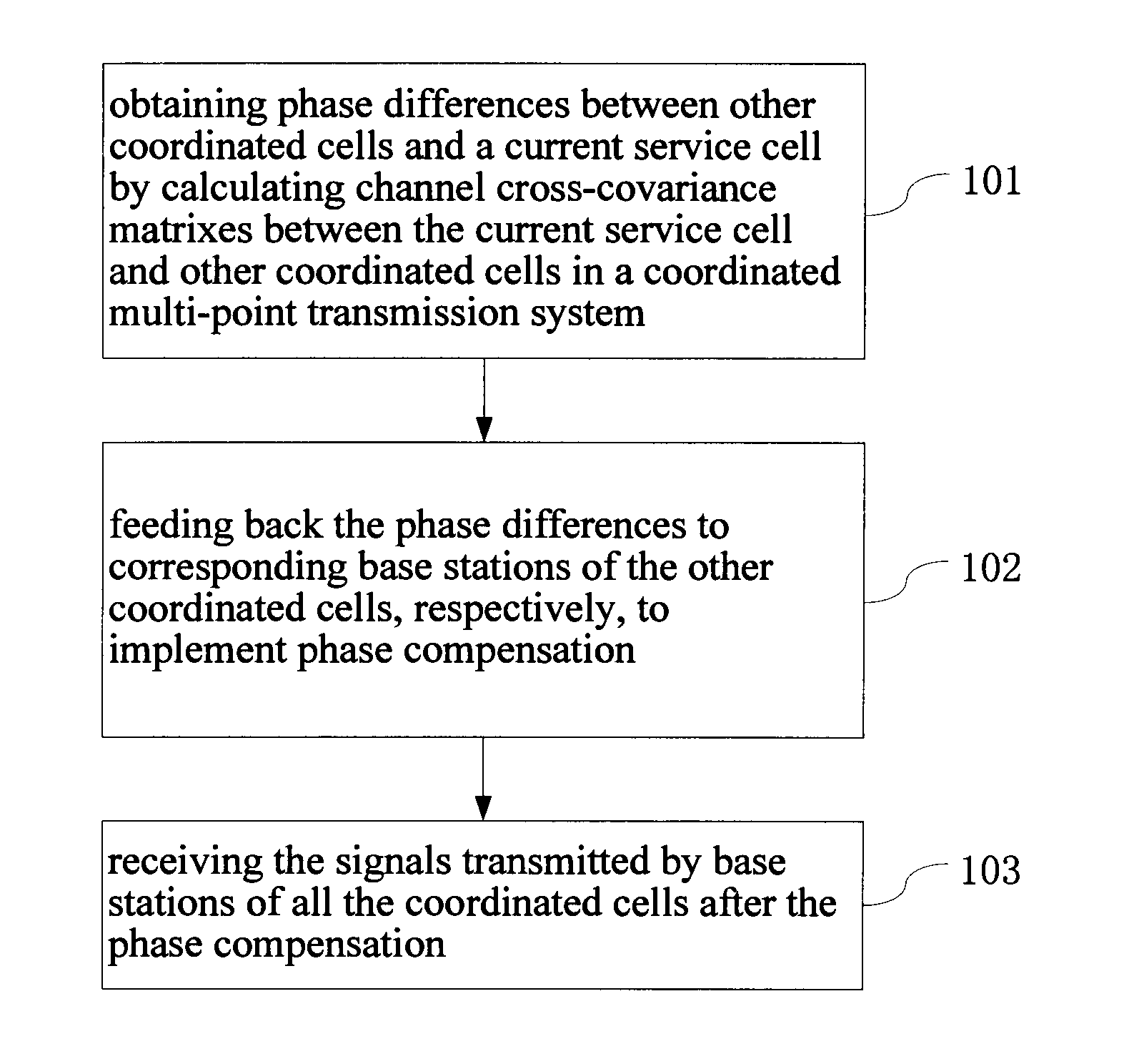
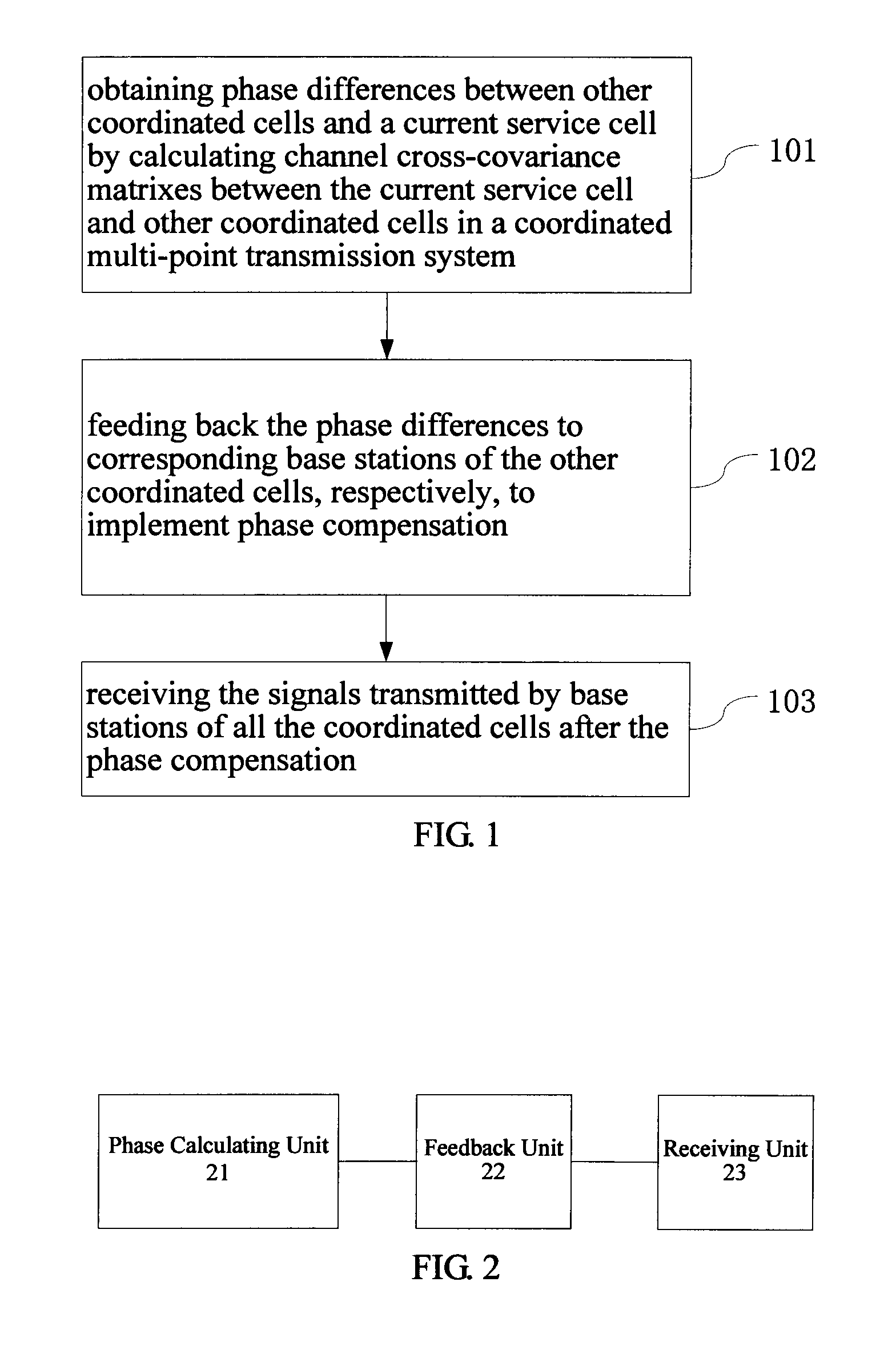
[0029]As shown in FIG. 1, a method for implementing coordinated multi-point transmission provided by the present embodiment includes the following steps:

[0030]101. Obtaining phase differences between other coordinated cells and a current service cell by calculating channel cross-covariance matrixes between the current service cell and the other coordinated cells in a coordinated multi-point transmission system.

[0031]Wherein the other coordinated cells are cells among all the coordinated cells in a coordinated multi-point transmission mode other than the current service cell. In a common situation, when an equipment feeds back the phase differences to a transmitting end, a phase reference cell will be determined first; and in the present embodiment, the current service cell in the coordinated multi-point transmission mode is taken as the phase reference cell.

[0032]Here, the cross-covariance matrixes between different coordinated cells can be constructed by means of the channel coeffi...

second embodiment

[0043]The method for implementing coordinated multi-point transmission provided in an embodiment of the present invention will be described below in detail with reference to a specific embodiment.

[0044]First, a scenario as below is assumed: the antenna configuration for each cell is 4-transmitting and 2-receiving, and a UE starts a CoMP coordinated transmission mode by means of a cell wireless scenario analysis; wherein, the original signal sent by a cell to the UE side is s(t), an expression in a time domain of a channel coefficient between a cell and a UE is h (t), and the corresponding expression in a frequency domain thereof is H(f); h(t) or H(f) herein can be obtained by channel estimation.

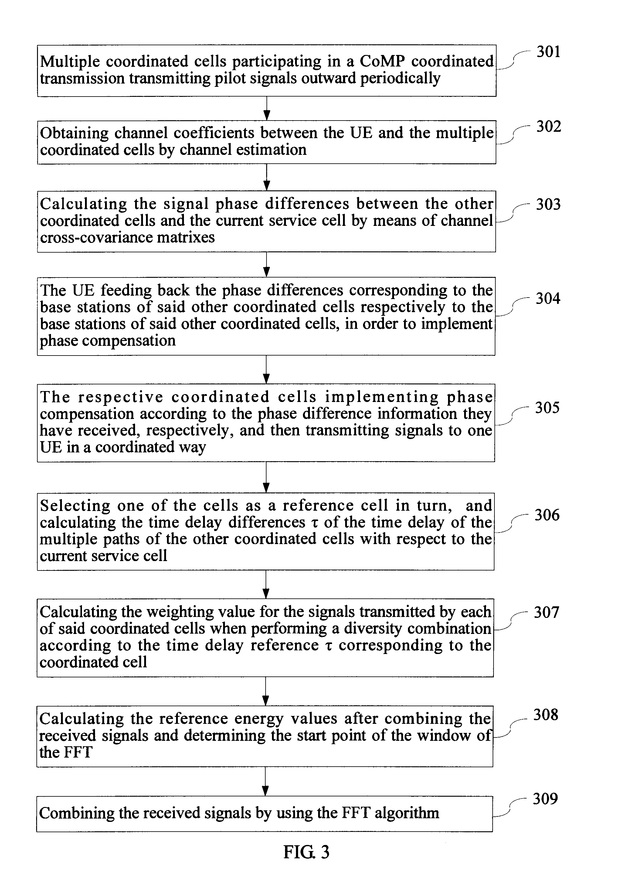
[0045]As shown in FIG. 3, the method for implementing coordinated multi-point transmission provided in the present embodiment specifically comprises the following steps:

[0046]301. Multiple coordinated cells participated in a CoMP coordinated transmission transmit pilot signals outwards period...

third embodiment

[0081]With regard to the method provided in the Second Embodiment, the present embodiment provides a user equipment for implementing coordinated multi-point transmission.

[0082]As shown in FIG. 4, the user equipment provided in the present embodiment comprises:

[0083]a phase calculating unit 41, for obtaining phase differences between other coordinated cells and a current service cell by calculating channel cross-covariance matrixes between the current service cell and the other coordinated cells in a coordinated multi-point transmission system; wherein the other coordinated cells are cells among all the coordinated cells other than the current service cell;

[0084]a feedback unit 42, for feeding back the phase differences to corresponding base stations of the other coordinated cells, respectively, to implement phase compensation;

[0085]a receiving unit 45, for receiving signals transmitted by the base stations of all the coordinated cells after the phase compensation,

[0086]In the presen...


PUM


Abstract

A method, equipment and system for implementing coordinated multi-point transmission are provided for resolving the problem that there exists phase noise in the signals received by a User Equipment (UE) end in coordinated multi-point transmission. The method for implementing coordinated multi-point transmission includes: obtaining phase differences between the current service cell and other coordinated cells by calculating channel cross-covariance matrixes between the current service cell and other coordinated cells in a coordinated multi-point transmission system (101); feeding back the phase differences corresponding to the base stations of said other coordinated cells respectively to the base stations of said other coordinated cells, in order to implement phase compensation (102); receiving the signals transmitted after the phase compensation by base stations of all the coordinated cells (103). The method, terminal and system provided by the embodiments of the present invention are applicable to the coordinated communication in various wireless networks.

Description

CROSS-REFERENCE TO RELATED APPLICATIONS[0001]This application is a continuation of International Application No. PCT / CN2010 / 078713, filed on Nov. 15, 2010, which claims priority to Chinese Patent Application No. 200910260758.8, filed with the Chinese Patent Office on Dec. 31, 2009, which is incorporated herein by reference in their entireties.FIELD OF THE INVENTION[0002]The present invention relates to the wireless communication technology, and particularly to a method, equipment and system for implementing coordinated multi-point transmission.BACKGROUND OF THE INVENTION[0003]In order to improve the Signal-to-Interference-and-Noise Ratio (SINR) of received signals of User Equipments (UEs) at the edges of a cell, a Coordinated Multi-point Process (CoMP), in which multiple base stations provide a coordinated transmission service to one UE simultaneously, is introduced into a LTE-A (Long Term Evolution—Advanced) system, thereby forming an architecture with distributed multiple antennae...

Claims


Application Information

Patent Timeline
IPC IPC(8): H04W92/00
CPCH04B7/024H04B7/0626H04L27/2695H04L27/2689H04L27/2657
Inventor SUN, GUOLINYE, FENGGAO, XIUJUAN
Owner HUAWEI TECH CO LTD
Why Eureka
Try Eureka