

Wire support frame for corrugated sign
a wire frame and corrugated technology, applied in the direction of instruments, traveling objects, display means, etc., can solve the problems of mallet or hammer, inability to bend, wooden signs suffer, etc., and achieve the effect of improving the holder, adding strength in the bends, and reducing the risk of damag
- Summary
- Abstract
- Description
- Claims
- Application Information
AI Technical Summary
Benefits of technology
Problems solved by technology
Method used
Image

Examples
second embodiment
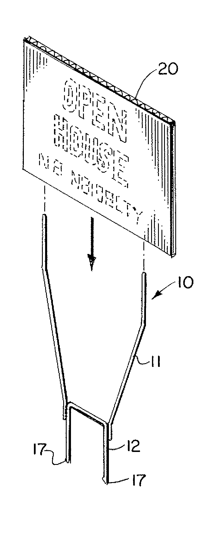
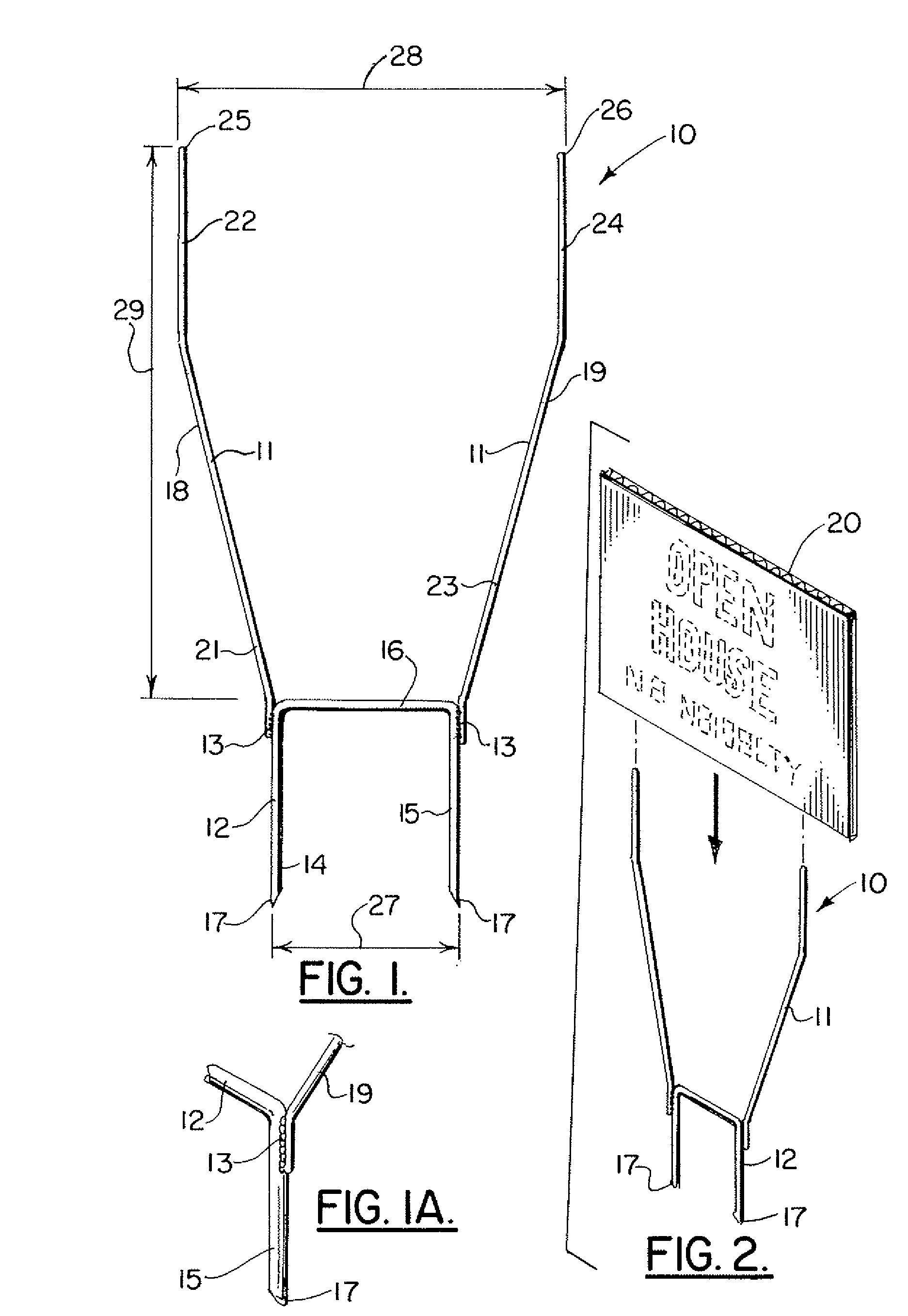
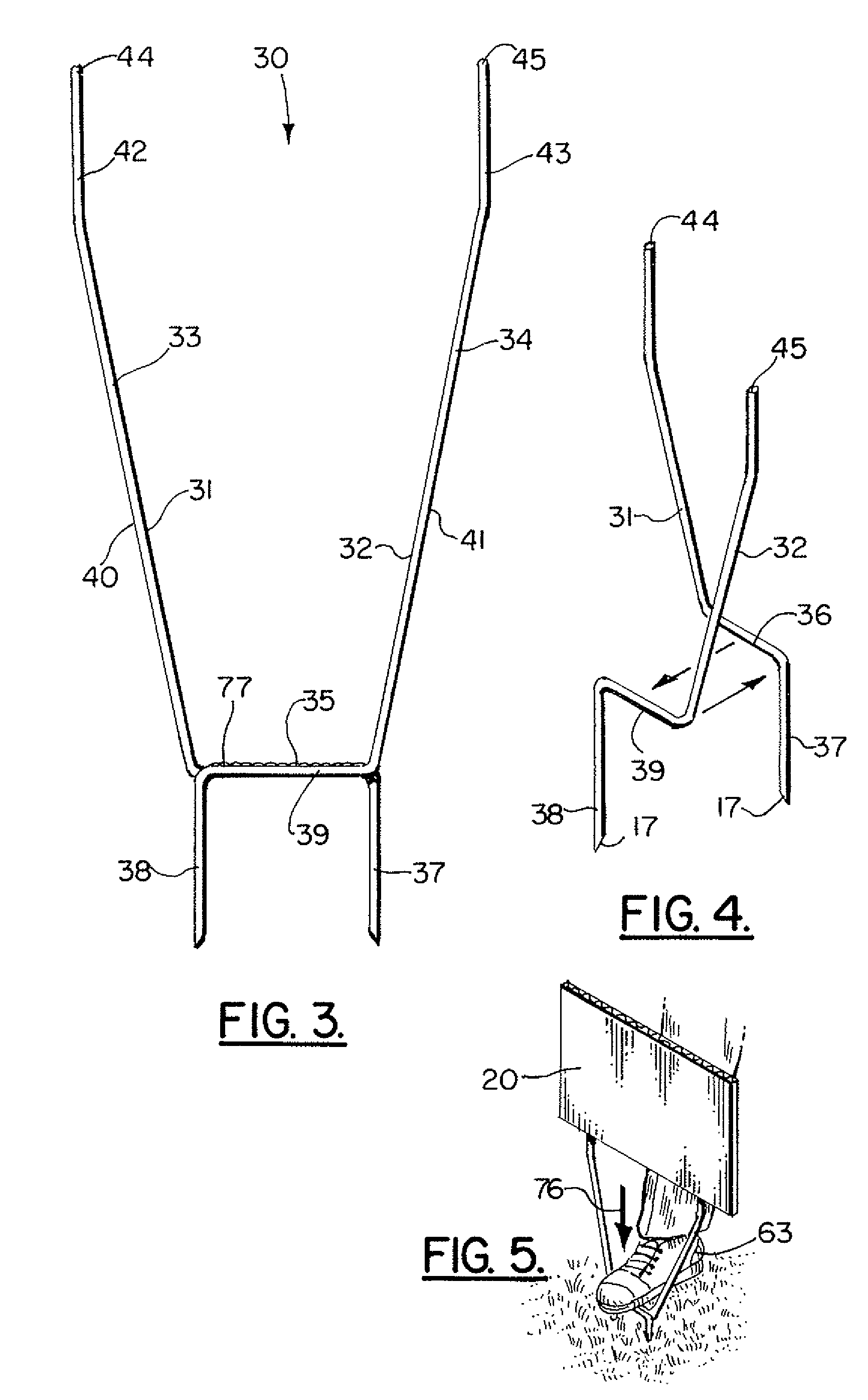
[0030]FIGS. 3-5 show the apparatus of the present invention, designated generally by the numeral 30. In the embodiment of FIGS. 3-4, sign support frame 30 includes a first section 31 and a second section 32. Each section 31, 32 provides an arm. The section 31 has arm 33. The section 32 has arm 34.
[0031]Each section 31, 32 has a transverse bar 36, 39 respectively. Weld 35 joins the sections 31, 32 together at transverse bars 36, 39. In FIG. 5, the foot of a user 63 is shown driving legs 37, 38 into the earth as indicated schematically by the numeral 76. Each section 31, 32 provides a leg. The section 31 has leg 37. The section 32 has leg 38. Each arm 33, 34 has a diagonally extending section. The arm 33 has diagonally extending section 40. The arm 34 has diagonally extending section 41.
[0032]Each arm 31, 32 has a vertically extending section that is mounted at the top of each of the diagonally extending sections 40, 41. The section 31 provides vertically extending section 42. The sec...
third embodiment
[0033]the apparatus of the present invention is designated generally by the numeral 46 in FIG. 7. Sign support frame 46 provides a left member 47 and a right member 48. Each of the members 47, 48 provides a leg 49, 54. The left member 47 is comprised of leg 49, diagonally extending section 50, vertically extending section 51, and smaller diameter rod 52 that is attached to the upper end portion of vertically extending section 51 with weld 61. Similarly, right member 48 includes leg 54, diagonally extending section 55, vertically extending section 56, and smaller diameter rod 57 that is attached to the upper end portion of vertically extending section 56 with weld 62.
[0034]A transverse bar 60 is attached to both left and right members 47, 48 using welds 53, 58 as shown in FIG. 6. For each of the left and right members 47, 48 a diameter 59A is provided that is much thicker than the diameter 59B for each of the smaller diameter rods 52, 57. The diameter 59B can be chosen so that smalle...
fourth embodiment
[0035]In FIG. 7, the apparatus of the present invention is indicated generally by the numeral 64. Sign support frame 64 includes left and right members 65, 66 each of which is preferably vertically positioned and a generally elongated linear member. A transverse bar 67 is attached to each of the members 65, 66 using a weld 68 as shown. At the upper end portion of each of the members 65, 66 there is provided a smaller diameter rod. Each of the smaller diameter rods 69, 70 is attached using a weld. Smaller diameter rod 69 is attached to left member 65 using weld 71. Similarly, smaller diameter rod 70 is attached to right member 66 using weld 72.
[0036]Each of the left and right members 65, 66 provides a leg section that can be driven into an underlying soil mass by a user 63. The user 63 simply places his or her foot on the transverse rod 67 and applies pressure downwardly in the direction of arrow 76 (as shown in FIG. 5). FIG. 5 is exemplary of installation of any of the embodiments o...
PUM
 Abstract
Description
Claims
Application Information