Locking cap system

a technology of locking cap and key combination, which is applied in the direction of threaded fasteners, screws, rod connections, etc., can solve the problem of desirably quickly removing the cap, and achieve the effect of reducing the deterioration over time and not easily being removed by unauthorizeds

Inactive Publication Date: 2008-10-21
KNOX
View PDF81 Cites 0 Cited by
  • Summary
  • Abstract
  • Description
  • Claims
  • Application Information

AI Technical Summary

Benefits of technology

[0010]Accordingly, a locking cap is desired for a standpipe that can be securely mounted so that it is not easily removed by unauthorized personnel. Additionally, such a locking cap desirably is quickly removed by authorized personnel under time pressures and mental anxiety. Moreover, such a locking cap should be relatively impervious to climatic elements such that deterioration over time is reduced.
[0011]Thus, the present invention provides a locking cap and key combination that is virtually tamperproof such that it cannot be removed without substantial destruction thereof, but which is not susceptible to inadvertent breakage. Moreover, the locking cap is easily removed at the appropriate time by authorized personnel utilizing a specially designed mating key arrangement. Furthermore, another aspect of the present invention provides a straightforward cap design which is easily and economically fabricated, and which is easily attached to secure a fire sprinkler system.
[0012]One feature of the present invention is the universal nature of the key and locking cap. While it is advantageous to prevent vandals and the like from removing the locking cap, the locking caps are configured with a unique locking mechanism which allows the fire department, or other authorized personnel, to use a single key to unlock every locking cap within their jurisdiction. This capability may prove important during crisis situations requiring rapid response. Specifically, the use of a single key eliminates the need to rifle through a variety of keys to find the proper key to remove the subject locking cap. Additionally, the locking caps may be serialized to empower a fire department or other entity with an ability track their location in the event of a lost, stolen or otherwise transferred locking cap.

Problems solved by technology

Additionally, such a locking cap desirably is quickly removed by authorized personnel under time pressures and mental anxiety.

Method used


Image

  • Locking cap system
  • Locking cap system
  • Locking cap system

Examples


Embodiment Construction

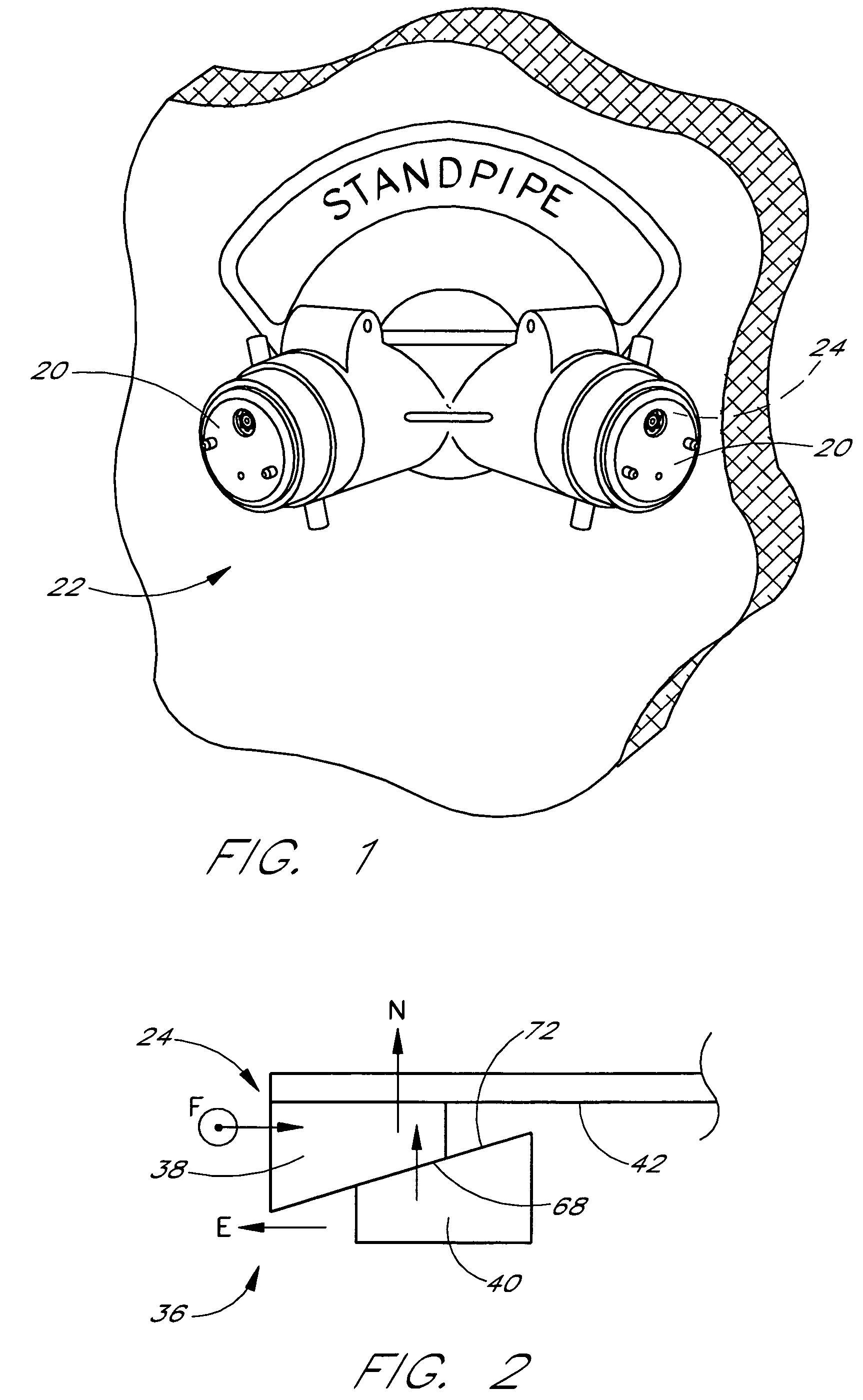
[0027]With reference initially to FIG. 1, a locking cap 20 is illustrated in engagement with a standard standpipe 22 connection. The pipe ends have internal threads for attaching fire hoses or the like. The illustrated locking caps are secured within the pipe end in engagement with the internal threads of the pipe ends and may be covered by the standard caps if desired. However, the illustrated locking caps preferably replace the standard caps. The illustrated standpipe 22 provides an exemplary environment for the locking cap and key combination having certain features, aspects and advantages in accordance with the present invention. Specifically, the present locking cap and key combination is designed to protect fire sprinkler system standpipe openings 24, or other similar openings, from debris which may be maliciously inserted into the openings and which may then damage or plug the associated sprinkler system when the system is charged during use.

[0028]It is understood, however, t...


PUM

PropertyMeasurementUnit
diameteraaaaaaaaaa
diameteraaaaaaaaaa
diameteraaaaaaaaaa

Abstract

A locking cap is selectively locked into place within a tubular opening, such as the open end of a standpipe used to charge a building sprinkler system. The locking cap has an expandable sleeve and a spreader member. As a key is turned, the spreader member is drawn into the expandable sleeve which is urged outward. The outward movement of the expandable sleeve increases a frictional component such that the expandable sleeve becomes frictionally locked within the tubular opening. The key has an end design that is complemented by an end of an actuator shaft such that the likelihood of unauthorized removal of the locking cap is reduced.

Description

CROSS REFERENCE TO RELATED APPLICATION[0001]This application is a continuation of U.S. application Ser. No. 10 / 273,894, filed Oct. 17, 2002 now U.S. Pat. No. 6,698,261 which is a continuation of U.S. application Ser. No. 09 / 247,665, filed on Feb. 9, 1999 now U.S. Pat. No. 6,487,882, issued Dec. 3, 2002, which claims priority from U.S. Provisional Application No. 60 / 074,156, filed on Feb. 9, 1998.BACKGROUND OF THE INVENTION[0002]1. Field of the Invention[0003]The present invention generally relates to a locking cap and key combination for open ends of plumbing components and, more specifically, to a protective locking cap and key combination for threaded openings in couplings, fixtures and the like. Even more specifically, the present invention relates to a locking cap and key combination for fire retardant sprinkler systems utilizing charging pipes.[0004]2. Description of the Related Art[0005]In fire protection systems that include automatic sprinkler systems having multiple sprinkl...

Claims


Application Information

Patent Timeline
Patent Type & Authority Patents(United States)
IPC IPC(8): B65D55/14A62C35/68B26D1/00B29B17/02
CPCA62C35/68B26D3/005Y10T403/7058Y10T403/7056Y10T70/5589Y10T137/5468
Inventor TREMPALA, DOHN J.
Owner KNOX
Why Eureka
Try Eureka