Heating and air conditioning service gauge

a technology for heating and air conditioning and service gauges, applied in heating types, instruments, lighting and heating apparatuses, etc., can solve the problems of inconvenient use of lookup charts, time-consuming, error-prone, etc., and achieve the effect of clear understanding

Active Publication Date: 2008-10-21
DIVERSITECH
View PDF5 Cites 11 Cited by
  • Summary
  • Abstract
  • Description
  • Claims
  • Application Information

AI Technical Summary

Benefits of technology

[0008]The pressure gauge of the present invention includes a sensor that measures changes in refrigerant pressure and produces an electronic pressure signal that is proportional to the measured refrigerant pressure. A battery powered microprocessor within the gauge receives the electronic pressure signal, converts the electronic pressure signal to a refrigerant pressure value in PSI or KPa, and digitally displays the refrigerant pressure value on the face of the gauge. In addition, the microprocessor can convert the refrigerant pressure value to a refrigerant saturated vapor equivalent temperature value (in

Problems solved by technology

Because HVAC systems respond very slowly and the pressure and the saturated vapor equivalent temperature must be continu

Method used


Image

  • Heating and air conditioning service gauge
  • Heating and air conditioning service gauge

Examples


Embodiment Construction

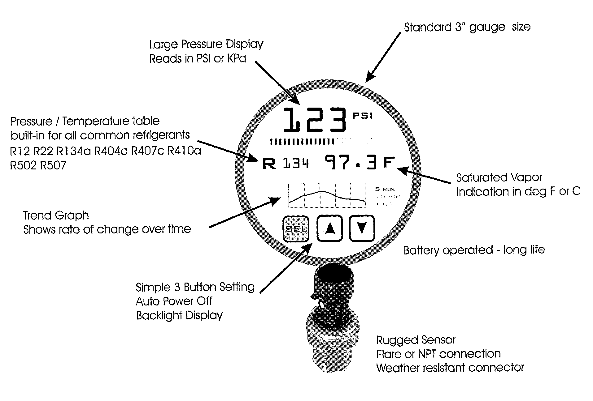
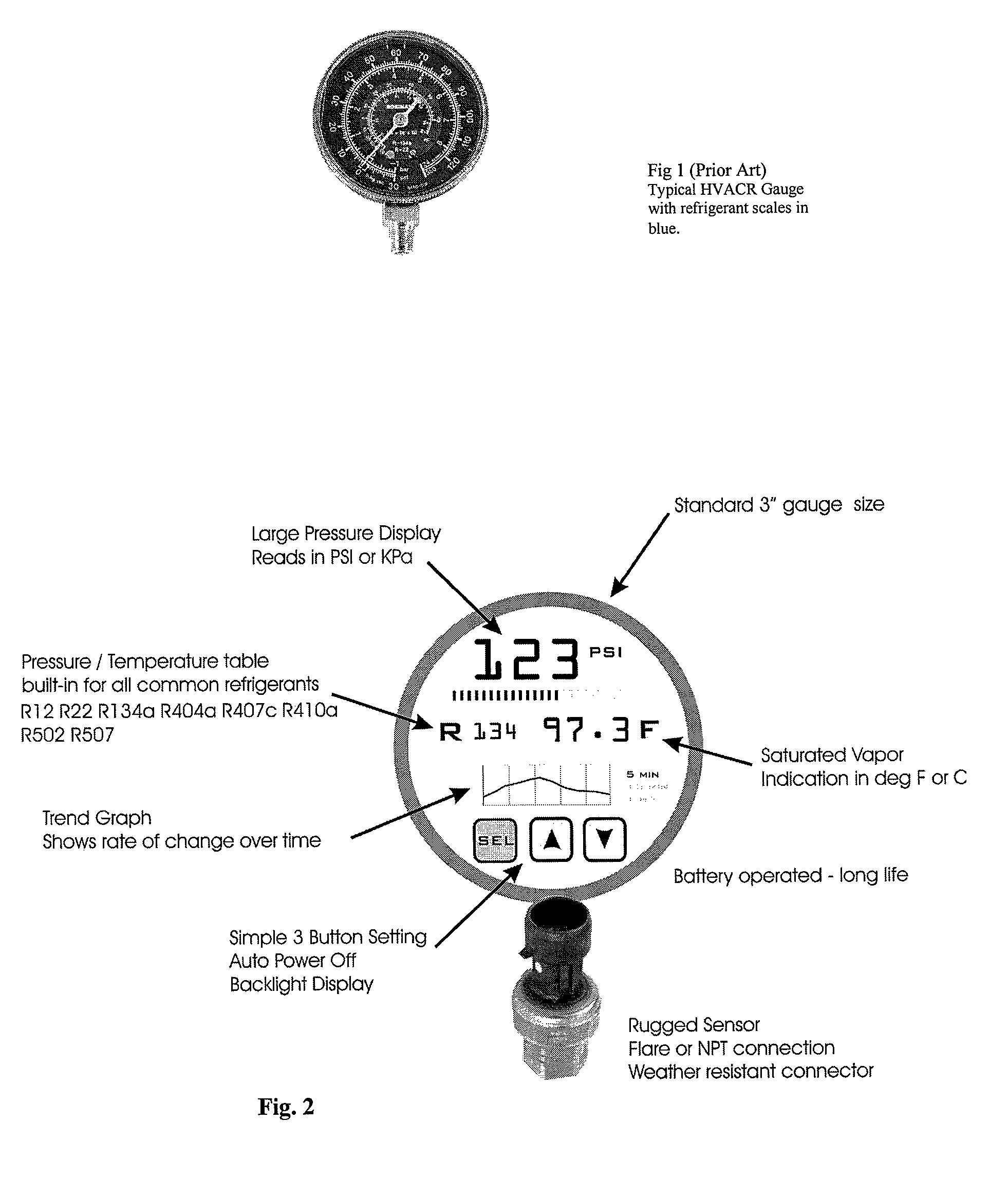
[0012]FIG. 2 shows a display for an electronic pressure gauge in accordance with the present invention. The size and shape of the pressure gauge is similar to the conventional prior art gauge shown in FIG. 1. The pressure gauge of the present invention comprises a pressure sensor that is in communication with a refrigerant pressure line of the HVAC system (not shown). The pressure sensor produces an electronic pressure signal that is proportional to the refrigerant pressure in the refrigerant line of the HVAC system. The pressure sensor is connected to a microprocessor powered by a battery. The microprocessor, including related electronics and software, converts the electronic pressure signal to a refrigerant pressure value that is shown on the display. For a particular refrigerant in the HVAC system, the microprocessor converts the electronic pressure signal to a refrigerant saturated vapor equivalent temperature value that is likewise shown on of the display.

[0013]From the refrige...


PUM


Abstract

A pressure gauge for determining refrigerant pressure and refrigerant saturated vapor equivalent temperature for a refrigerant in an HVAC system.

Description

CLAIM OF PRIORITY[0001]This application claims priority from U.S. Provisional Patent Application Ser. No. 60 / 746,720 filed on May 8, 2006, which is incorporated herein in its entirety.FIELD OF THE INVENTION[0002]This invention relates to a service gauge used for installing and servicing an HVAC system.BACKGROUND OF THE INVENTION[0003]HVAC service personnel must measure the system refrigerant pressure in order to install or service a HVAC system. This measurement is accomplished with an analog pressure gauge. Typically, the gauges are mechanical and contain a curved tube, which bends in response to the applied pressure. Connected to the tube are series of watch-like gears that connect and rotate the indicating needle located on the front of the gauge.[0004]Gauges can either be permanently attached to the equipment or incorporated into portable tools or manifolds. Normally, a manifold or gauge manifold holds two gauges for pressure measurement and includes valves for installation or r...

Claims


Application Information

Patent Timeline
IPC IPC(8): G01L9/00
CPCF24F11/001F24F2011/0043F24F11/30F24F2110/00F24F2140/12F24F11/52F24F11/63
Inventor WARD, CHARLES BARRY
Owner DIVERSITECH
Why Eureka
Try Eureka