Robot cleaner coordinates compensation method and a robot cleaner system using the same

a robot cleaner and robot technology, applied in the field of robot cleaners, can solve the problems of high cost, gyro sensor usually has a detection error ranging from 5% to 10%, and the robot cleaner may not follow the planned path accurately, so as to achieve the effect of improving the path following

Inactive Publication Date: 2008-10-21
SAMSUNG GWANGJU ELECTRONICS CO LTD
View PDF20 Cites 39 Cited by
  • Summary
  • Abstract
  • Description
  • Claims
  • Application Information

AI Technical Summary

Benefits of technology

[0010]The present invention has been developed in order to solve the above drawbacks and other problems associated with the conventional arrangement. An aspect of the present invention is to provide a method for compensating for a coordinate system of a robot cleaner such that the robot cleaner can effectively follow a planned running direction using angle sensor such as a gyro sensor.
[0011]It is another aspect of the present invention to provide a robot cleaner which uses a coordinate compensation method such that the robot cleaner can effectively follow a planned running direction using angle sensor such as a gyro sensor.
[0019]With the coordinates compensation method of a robot cleaner according to the present invention, the origin of the robot cleaner is realigned with reference to the coordinate system of the recharging station when the accumulative error of the angle sensor exceeds a predetermined level. Accordingly, the accumulative error of the angle sensor can be compensated to ‘0’ periodically, and therefore, the robot cleaner's path following is improved.
[0020]Additionally, with the robot cleaner system according to the present invention, because the origin of the robot cleaner can be realigned with reference to the coordinate system of the recharging station by use of distance sensors of the robot cleaner when the accumulative error of the angle sensor exceeds a predetermined level, the robot cleaner's path following is improved.

Problems solved by technology

Using the CCD camera, however, causes problems of high costs because it requires the system to fast process a large amount of data.
However, such a gyro sensor usually has a detection error ranging from 5% to 10%, and a problem occurs as the robot cleaner repeats rotation operation because the detection error accumulates.
As a result, the robot cleaner may not follow the planned path accurately.

Method used


Image

  • Robot cleaner coordinates compensation method and a robot cleaner system using the same
  • Robot cleaner coordinates compensation method and a robot cleaner system using the same
  • Robot cleaner coordinates compensation method and a robot cleaner system using the same

Examples


Embodiment Construction

[0029]Certain embodiments of the present invention will be described in greater detail with reference to the accompanying drawings.

[0030]In the following description, same drawing reference numerals are used for the same elements even in different drawings. The matters defined in the description such as a detailed construction and elements are nothing but the ones provided to assist in a comprehensive understanding of the invention. Thus, it is apparent that the present invention can be carried out without those defined matters. Also, well-known functions or constructions are not described in detail since they would obscure the invention in unnecessary detail.

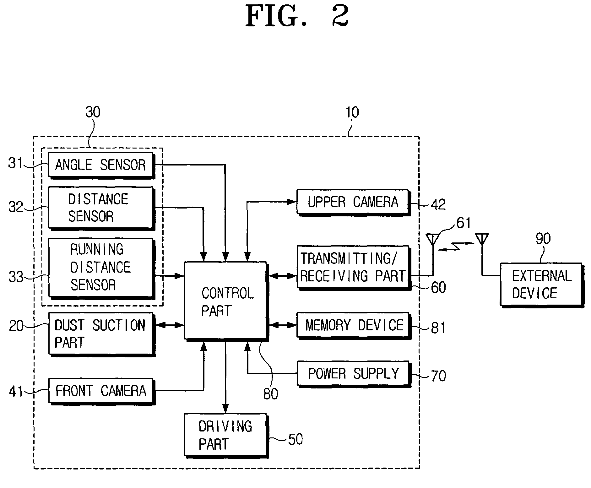
[0031]Referring to FIGS. 2 and 3, a robot cleaner 10 according to an embodiment of the present invention includes a dust suction part 20, a sensor part 30, a front camera 41, an upper camera 42, a driving part 50, a transmitting / receiving part 60, a power supply 70, a memory device 81 and a control part 80, all of which are arr...


PUM


Abstract

A coordinates compensation method of a robot cleaner using an angle sensor compensates coordinates of the robot cleaner with reference to absolute coordinates of a recharging station, so as to improve robot cleaner's path following. The robot cleaner is in a standby mode at the recharging station, and moves to an operation area to perform a given job. The robot cleaner stops the given job upon determining an accumulative angle exceeding a predetermined level, and returns to the recharging station. Current coordinates of the robot cleaner are aligned with reference coordinates of the recharging station, and the robot cleaner moves to a previous spot where it was before it returns to the recharging station, and resumes the work from where it stopped.

Description

CROSS-REFERENCE TO RELATED APPLICATIONS[0001]This application claims the benefit of Korean Patent Application No. 2004-81200 filed Oct. 12, 2004, in the Korean Intellectual Property Office, the disclosure of which is incorporated herein by reference.BACKGROUND OF THE INVENTION[0002]1. Field of the Invention[0003]The present invention relates to a robot cleaner for automatic operation, and more particularly, to a coordinate compensation method for an automatic robot cleaner.[0004]2. Description of the Related Art[0005]A robot cleaner generally determines the target area of cleaning operation using sensors such as ultrasound sensor mounted on a main body, or in accordance with information input by a user. The robot cleaner then plans a most efficient path of cleaning operation. According to the plan, the robot cleaner runs and drives a dust sucking part to draw in dust from the floor.[0006]One way of moving such a robot cleaner along the planned path is that the robot cleaner calculat...

Claims


Application Information

Patent Timeline
Patent Type & Authority Patents(United States)
IPC IPC(8): B08B7/04G05D1/00G05D1/02
CPCG05D1/0219G05D1/0225G05D1/0246G05D1/027G05D1/0272G05D1/024G05D1/0242A47L2201/04G05D2201/0203G05D2201/0215A47L2201/022G05D1/0255G05D1/0234A47L9/00G05D1/021A47L9/28A47L11/00A47L11/40G05D1/02A47L2201/00
Inventor SONG, JEONG-GONJEUNG, SAM-JONGKIM, KI-MANLEE, JU-SANGKO, JANG-YOUNLIM, KWANG-SOO
Owner SAMSUNG GWANGJU ELECTRONICS CO LTD
Why Eureka
Try Eureka