Bioreactor system for biological degradation of oily sludge

a biological degradation and bioreactor technology, applied in the direction of filtration separation, multi-stage water/sewage treatment, separation process, etc., can solve the problems of air pollution, inability to achieve biological treatment systems, and inability to biologically treat some organic pollutants such as pcbs, so as to reduce the fouling of ultrafiltration membranes

Inactive Publication Date: 2008-10-21
NAVY AS REPRESENTED BY THE UNITED STATES OF AMERICA SEC OF THE
View PDF7 Cites 8 Cited by
  • Summary
  • Abstract
  • Description
  • Claims
  • Application Information

AI Technical Summary

Benefits of technology

[0013]At the end of a reaction cycle, an aeration system at the bottom of the reactor tank and recirculation pump are turned off from a controller and solids settle to the bottom of the reactor tank. After settling to the bottom of the reactor tank, supernatant and solids are passed through a bag filter and an ultrafiltration unit. Suspended solids which are primarily biomass are recycled to the receiving tank. The bag filter which is upstream from the ultrafiltration unit removes larger particles which reduces fouling of the ultrafiltration membranes. Clean effluent from the ultrafiltration unit is sent to a 20,000 gallon holding tank.

Problems solved by technology

Although significant progress has been made in treating compounds once considered recalcitrant, biological treatment of some organic pollutants, such as PCB's is not yet practicable.
High concentrations of heavy metals, solvents, salt, and extremes of pH or temperature will hinder and in some cases poison biological treatment systems.
Vigorous aeration of a treatment reactor produces air emissions and the degradation process itself may produce volatile compounds.
Since oily sludge cannot be recycled or burned, it is drummed and stored at landfills.
Due to increasing costs, long-term liability, and restrictions on landfill disposal, there is an urgent need for a cost effective on-site treatment.

Method used


Image

  • Bioreactor system for biological degradation of oily sludge
  • Bioreactor system for biological degradation of oily sludge
  • Bioreactor system for biological degradation of oily sludge

Examples


Embodiment Construction

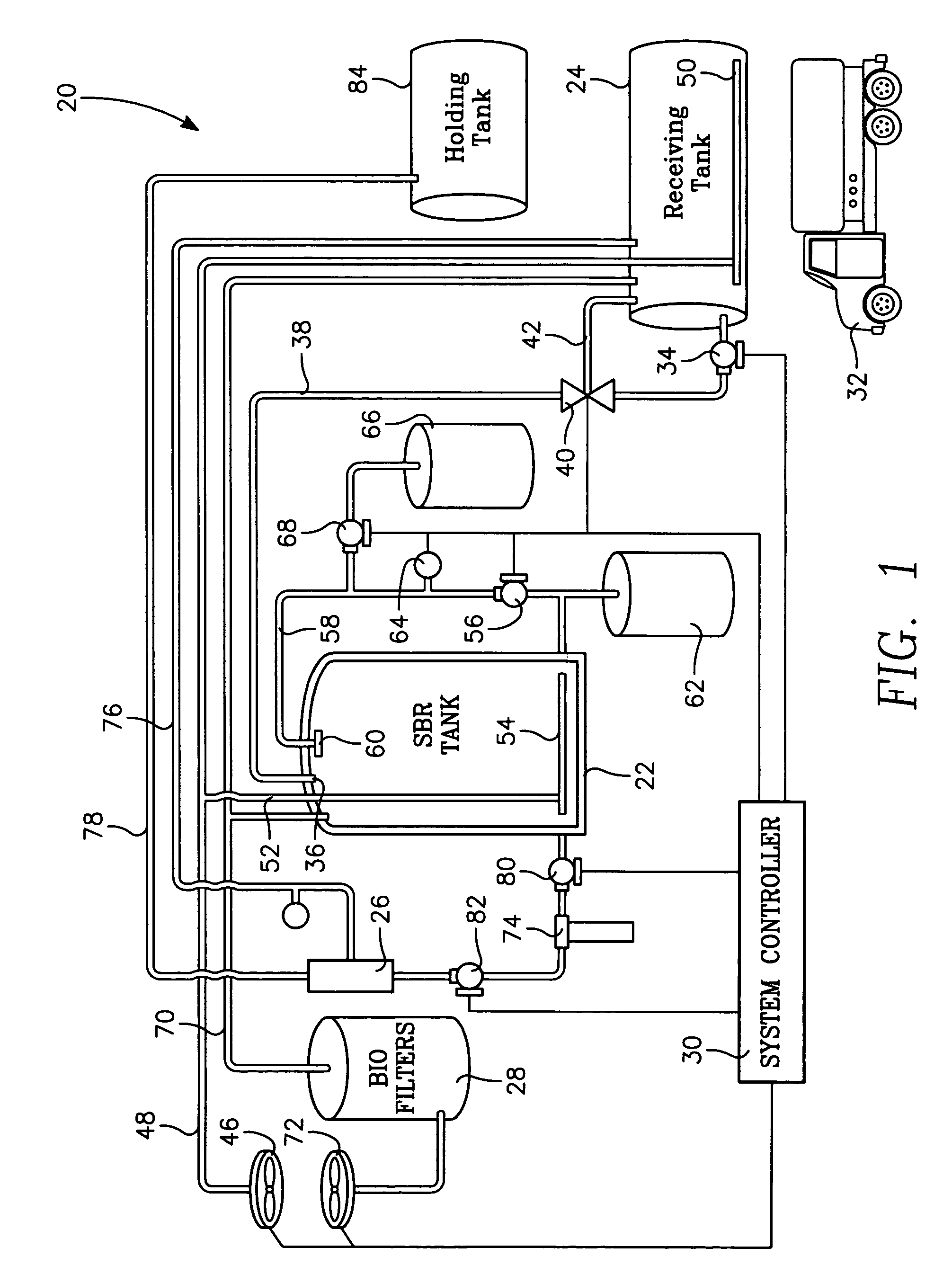
[0021]Referring to FIG. 1, FIG. 1 illustrates a schematic diagram of bioreactor system / installation 20 and its associated components. The major components are of the reactor installation are the sequencing batch reactor tank / bioreactor tank 22, a sludge receiving tank 24, an ultrafiltration unit 26, compost filled biofilters 28, and a controller / control room 30. The nature of the waste to be treated, and capacity of the tanks requires the bioreactor installation 20 to be installed on a concrete pad with secondary containment.

[0022]The raw material for treatment by bioreactor tank 22 is oily sludge. Sources at military facilities which provide the oily sludge include but are not limited to fuel tank bottoms, pump stations, wash racks, and oil / water separators. Oily sludge is delivered via a dedicated pipeline or vacuum trucks 32 to receiving tank 24, where the oily sludge is diluted and run through a trash pump 34 to produce a homogenous slurry. The discharge port of trash pump 34 is...


PUM

PropertyMeasurementUnit
time periodaaaaaaaaaa
pHaaaaaaaaaa
timeaaaaaaaaaa

Abstract

A 10,000 gallon sequencing batch reactor tank for the on-site bio-degradation of oily sludge. Bacteria already present in and adapted to oily sludge degrade the hydrocarbons found in oily sludge within two weeks from 20,000 ppm to less than 100 ppm. A degradation cycle requires 5 days. After five days a recirculation pump and aeration system are turned off and solids are allowed to settle to the bottom of the tank. An ultrafiltration unit connected to the tank requires approximately 16 hours to process the contents of the reactor tank.

Description

[0001]This application is a continuation of U.S. patent application Ser. No. 10 / 943,653, filed Sep. 3, 2004.BACKGROUND OF THE INVENTION[0002]1. Field of the Invention[0003]The present invention relates generally to the disposal of oily sludge. More specifically, the present invention relates to an apparatus and method for the biological degradation of oily sludge with the apparatus comprising a sequencing batch reactor for the on-site degradation of oily sludge.[0004]2. Description of the Prior Art[0005]Biological treatment facilities and processes are increasingly used to treat a wide variety of organic rich waste streams. The most common application of biological treatment of waste is sewage treatment. Food processors, feed lots, the paper industry, oil refineries, and the automotive industry often use on-site biological treatment processes for high biological demand waste. In most applications, biological treatment facilities / systems are designed to promote the growth of naturall...

Claims


Application Information

Patent Timeline
Patent Type & Authority Patents(United States)
IPC IPC(8): C02F3/34B01D35/00C02F9/00C02F3/00C02F3/02C02F3/30
CPCC02F3/1263C02F11/02C02F1/444C02F2101/32C02F2209/06C02F2305/06Y02W10/20Y02W10/10
Inventor MAGA, GERARDO F.GOETZ, FREDERICK E.
Owner NAVY AS REPRESENTED BY THE UNITED STATES OF AMERICA SEC OF THE
Why Eureka
Try Eureka