
Apparatus and method for droplet measurements

a technology of droplet measurement and measuring apparatus, which is applied in the direction of measurement apparatus housing, capacity measurement calibration, disinfection, etc., can solve the problems of inability to monitor the visual arrival of a tiny drop to a destination substrate, difficulty in consistent dispensing, and inability to accurately diagnose the problem, etc., to achieve close correlation

Active Publication Date: 2008-10-21
ALLEGRO TECH
View PDF6 Cites 17 Cited by
  • Summary
  • Abstract
  • Description
  • Claims
  • Application Information

AI Technical Summary

Benefits of technology

"The invention provides a method for monitoring and measuring the volume of liquid droplets as they are discharged from a liquid dispensing system. This is achieved by using the liquid to form a capacitor, where the change in capacitance is measured as the liquid droplet passes through the nozzle. The method can be calibrated and can be used to control the formation of the droplet and detect leaks in the system. The invention also provides an apparatus for carrying out the monitoring and measuring process. The technical effects of the invention include improved accuracy in measuring the volume of liquid droplets and improved detection of leaks in the system."

Problems solved by technology

The wide variety of the mechanical properties of liquids and the very nature of many biological liquids often make consistent dispensing difficult.
For example, failure to dispense a drop may lead to an incorrect result of a medical test and consequently to incorrect diagnosis.
The reason is that in many cases the operator cannot readily monitor visually arrival of a tiny drop to a destination substrate, in particular, if the destination substrate is not flat.
This adds to the user discomfort even if the dispenser functions properly as the user cannot readily satisfy himself / herself in this by simple visual monitoring.
It is difficult to fulfil challenging requirements for a successful system for measurement of droplet volume during dispensing.
For many applications the ideal system must measure the volume in non-contact mode meaning that direct transfer of the drop to a measurement device such as microbalance is not an option.
The disadvantage of this method is that it is based on the absorption of electromagnetic radiation (in practice light) by the droplet.
It will therefore not work for liquids that do no absorb the radiation well.
For a range of applications where minute droplets of liquids with a broad range of optical properties need to be dispensed, the method may be inappropriate.
One of the disadvantages is that it is sensitive to external electromagnetic noise, e.g. noise at 50 or 60 Hz frequency.
This increases the chances of missing the exit hole and thus leaving the drop attached to the wall of the inner chamber.
Another disadvantage is that in order to increase the charge carried by the droplet and thus improve the sensitivity of the instrument, it is often necessary to apply as high a voltage to the dispenser as possible.
This may create further complications; e.g. the risk of destroying a charge sensitive amplifier connected to the pail, the risk of the malfunctioning of high voltage equipment with consequent danger for the operator, etc.
In some cases there is further complication related to the size of the drop.
This could be comparable to the size of the pail and therefore add to inaccuracy of the drop volume measurement as the jet segment can no longer be considered as a small charge surrounded from all the sides by the inner chamber of the Faraday pail.
To summarise, at present the issue of reliable detection and measurement of the volume of droplets dispensed is still not entirely resolved.
It is suggested that the lack of a commonly acceptable measurement technology impedes wider use of low-volume liquid handling equipment.

Method used


Image

  • Apparatus and method for droplet measurements
  • Apparatus and method for droplet measurements
  • Apparatus and method for droplet measurements

Examples


Embodiment Construction

[0058]The invention beneficially utilises the often overlooked fact that in a typical low volume non-contact mode dispenser the drop is often ejected in the form of a jet segment or elongate drop or droplet rather than a sphere. As explained above, the sphere is then formed out of the segment due to surface tension. It is true to say that if the pressure difference at which the drop is ejected is low, the drop can still grow in sphere-like shape at the end of the nozzle. However, in this case the drop tends to remain attached to the nozzle up to a relatively large volume per drop dispensed. Therefore, to achieve detachment of the drop from the nozzle, the drop often needs to be a ejected at a relatively high pressure and thus it forms a jet. For more details on this one can consult the specifications of the following patent applications, namely: U.S. patent application Ser. No. 09 / 709,541 (Shvets et al), filed 13 Nov., 1990; PCT patent Application No. PCT / IE02 / 00039 (Shvets et al), ...


PUM

PropertyMeasurementUnit
carrying frequencyaaaaaaaaaa
volumesaaaaaaaaaa

Abstract

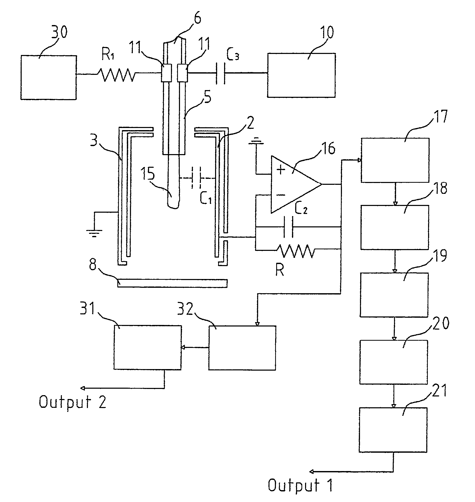
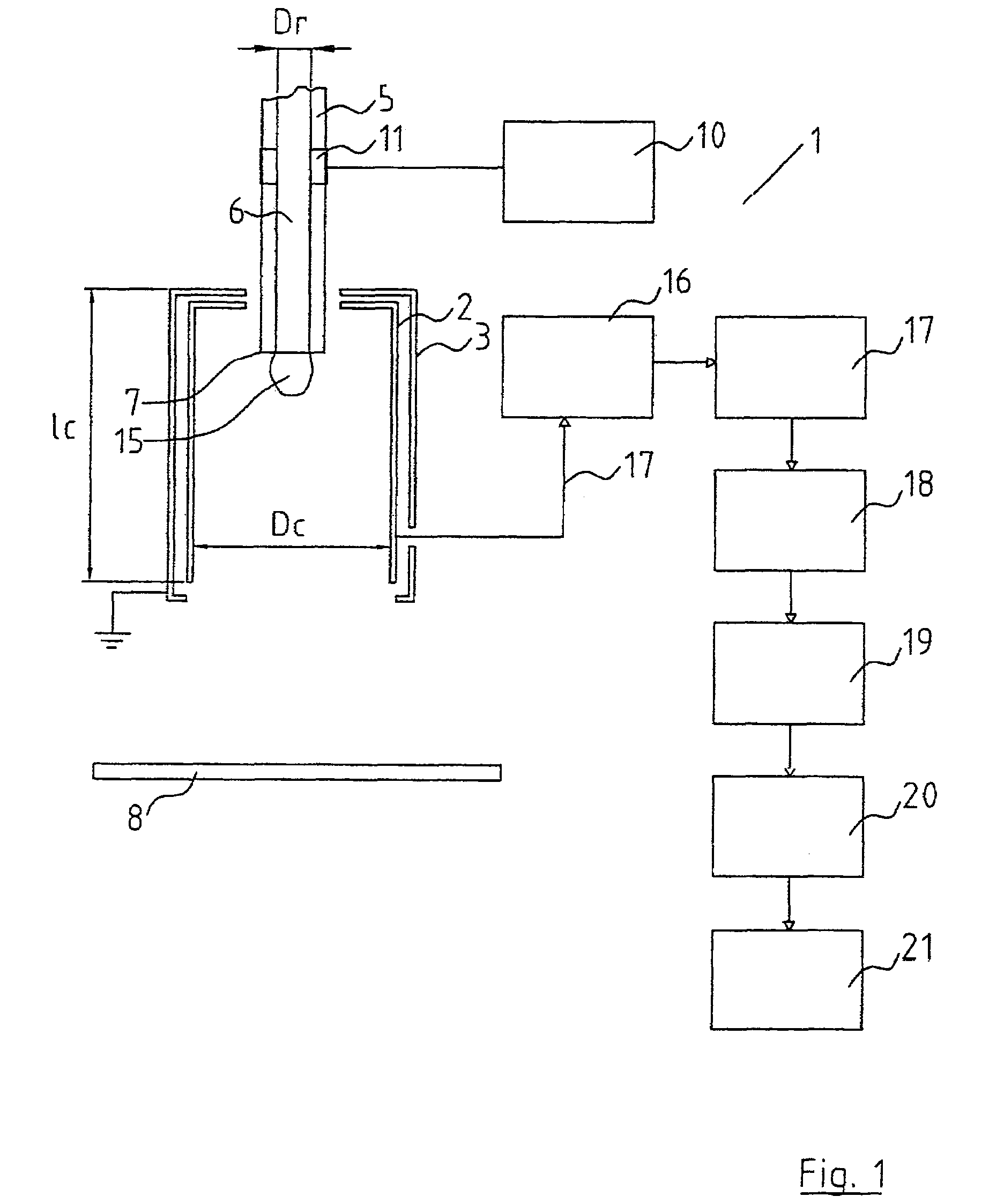
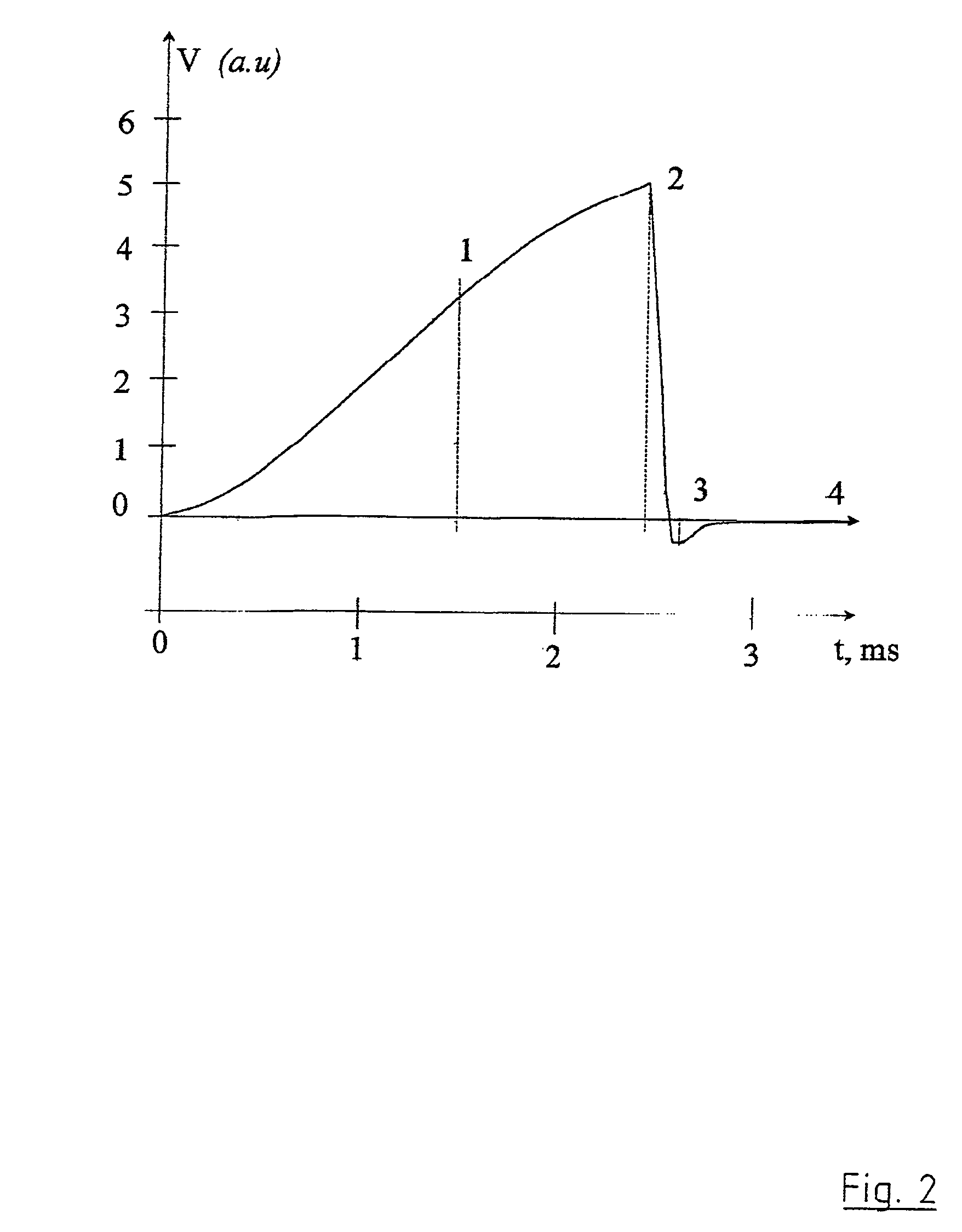
There is provided a liquid droplet monitoring and measuring apparatus (1) for a liquid droplet dispensing system having a nozzle (5) with a dispensing tip (7). The apparatus (1) comprises an inner chamber (2) surrounded by an outer shield (3), preferably not in contact with each other. An RF oscillator electrically energizes the liquid through an electrode (11). The inner chamber (2) is connected through pre-amplifiers (16), band pass filters (17conditioning amplifier (20) to a signal read-out device (21). The operation of the apparatus is based on the measurement of the capacitance between the nozzle (5) and the inner chamber (2). As a droplet (15) grows on the dispensing tip (7), the capacitance between the nozzle (5) and the inner chamber (2) increases. Therefore, the signal detected and received by the signal read-out device (21) changes. This change is directly related to the volume of the droplet which can therefore be measured. In another embodiment, the liquid is not energized but is used to change the dielectric constant of a capacitor formed by, for example, the nozzle (5) and a substrate.

Description

FIELD OF THE INVENTION[0001]The present invention relates to a liquid droplet monitoring and measuring apparatus for use with a droplet dispenser of the type comprising a nozzle having a dispensing tip and means for delivering the liquid under pressure through the nozzle onto a receiving substrate. Further, the invention provides a method of monitoring and measuring the volume of a liquid droplet as it is being dispensed from a liquid dispensing system comprising a nozzle having a dispensing tip.BACKGROUND OF THE INVENTION[0002]The present invention is generally related to liquid handling systems for dispensing and aspirating small volumes of liquids of the order of 1 ml and smaller and in particular of the order of 50 microliters and smaller. Liquid handling systems are being provided and will be provided in the future for the dispensation of droplets of even smaller sizes. The present invention is particularly directed to liquid handling systems used in life science, medical and p...

Claims


Application Information

Patent Timeline
Patent Type & Authority Patents(United States)
IPC IPC(8): G01N25/08B01L3/02B05B1/00G01F1/00G01F22/00G01N35/10
CPCB01L3/0241G01F22/00B01L2200/061B01L2300/0627G01N35/1016G01N2035/1025
Inventor SHVETS, IGORSHVETS, ALEXANDERMAKAROV, SERGEIOSING, JUERGENFRANKEN, CECILIA
Owner ALLEGRO TECH
Learn More