Supercharge Your Innovation With Domain-Expert AI Agents!

Antenna and an antenna feed structure

a technology of antenna feed and antenna, applied in the direction of antenna details, non-resonant long antennas, antennas, etc., can solve problems such as possible reactive imbalan

Active Publication Date: 2008-10-21
HARRIS GLOBAL COMM INC
View PDF33 Cites 18 Cited by
  • Summary
  • Abstract
  • Description
  • Claims
  • Application Information

AI Technical Summary

Benefits of technology

The invention is a three-dimensional antenna with a unique feed structure that allows for operation at frequencies above 200 MHz. The antenna has a plurality of conductive elements on the surface of a dielectric core, which is surrounded by a metallised sleeve. The antenna elements are connected together at one end of a feed structure, which passes through the core. The feed structure can be a coaxial transmission line or a printed circuit board. The antenna has a matching network that includes a shunt capacitance and an inductance, which can be used to transform the impedance of the antenna to match the impedance of the equipment to which it is connected. The antenna has a length of coaxial transmission line and a laminate board that can be easily inserted into the antenna core and connected to the conductor elements on the surface of the core using solder paste or solder preforms. The mechanical connection between the laminate board and the coaxial line can be made by way of lugs on the shield conductor of the coaxial line or by swaging the shield conductor outwardly to make a connection to the conductive layer on the board.

Problems solved by technology

Although the balun sleeve generally serves to achieve such balance, some reactive imbalance may occur owing to constraints on the characteristic impedance of the coaxial feeder structure and on its length.

Method used


Image

  • Antenna and an antenna feed structure
  • Antenna and an antenna feed structure
  • Antenna and an antenna feed structure

Examples


Embodiment Construction

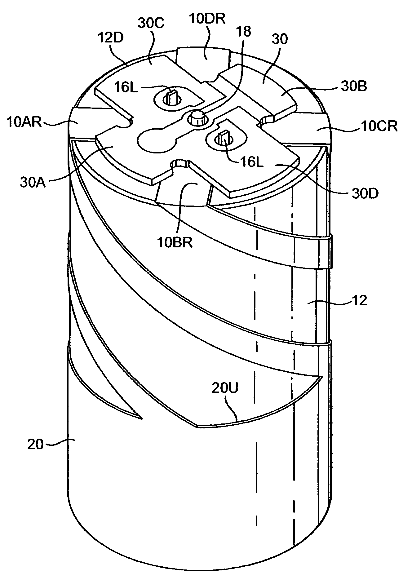
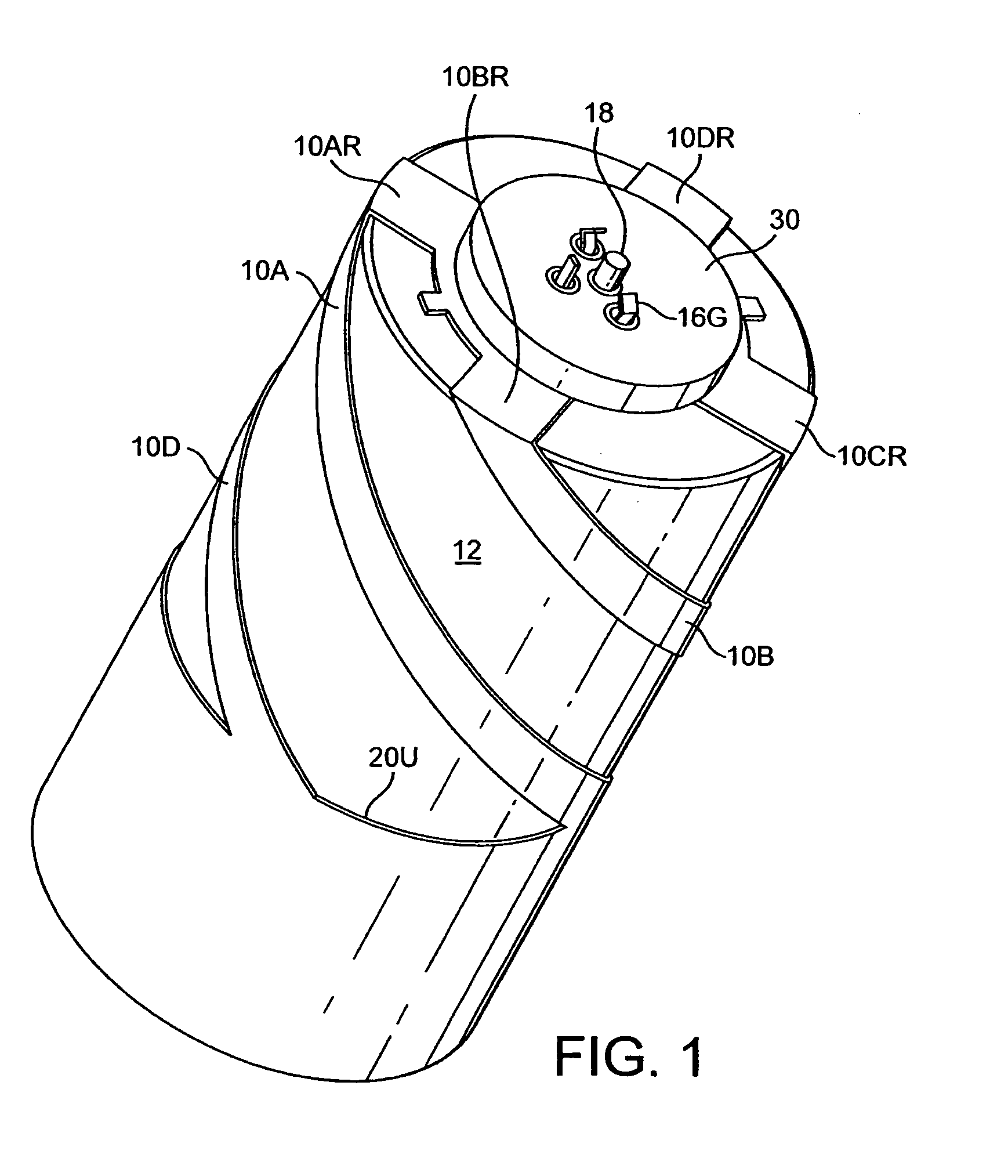
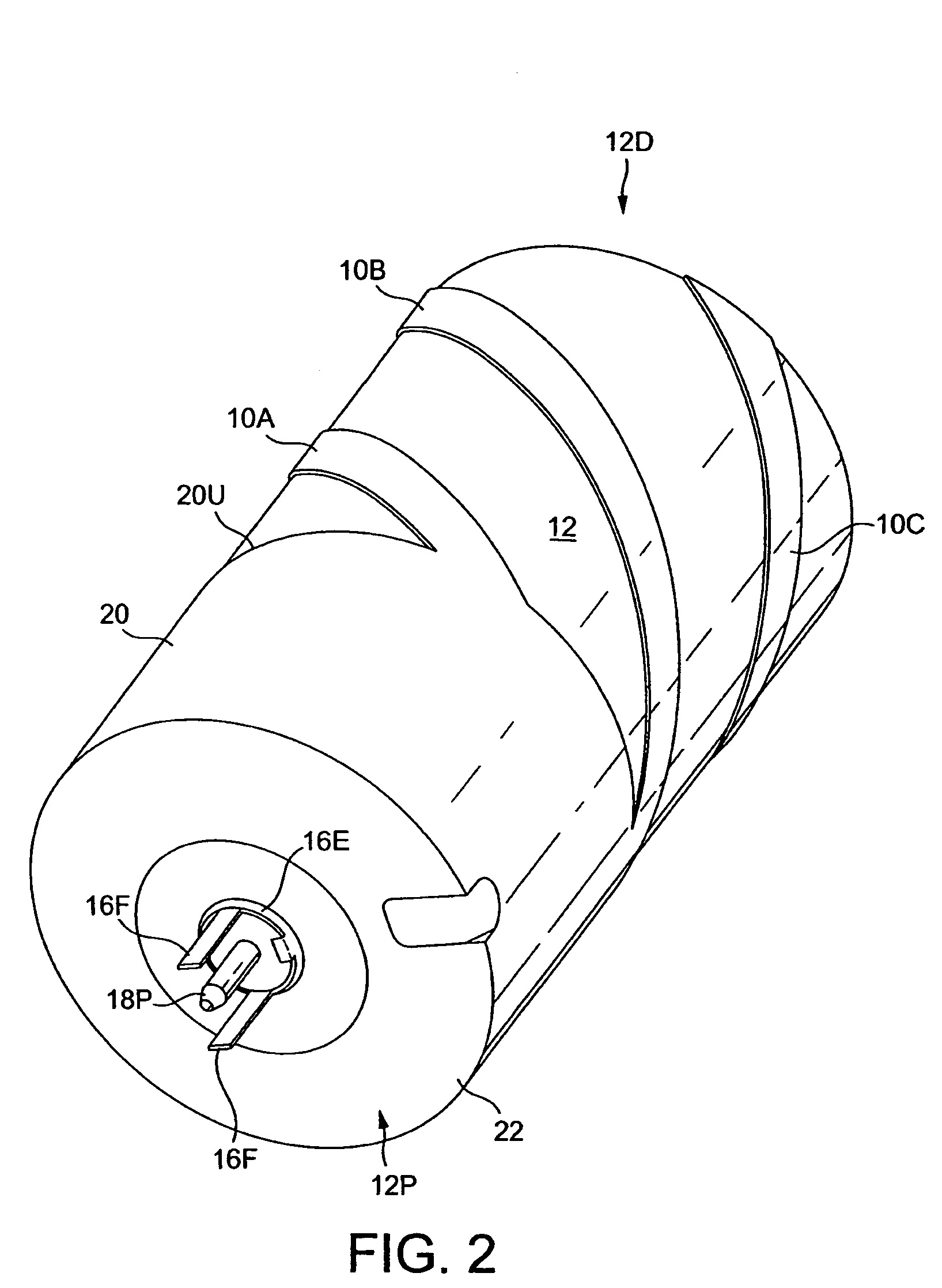
[0047]A first antenna in accordance with the invention has an antenna element structure with four axially coextensive helical tracks 10A, 10B, 10C, 10D plated or otherwise metallised on the cylindrical outer surface of a cylindrical ceramic core 12.

[0048]The core has an axial passage in the form of a bore 12B extending through the core 12 from a distal end face 12D to a proximal end face 12P. Both of these faces are planar faces perpendicular to the central axis of the core. They are oppositely directed, in that one is directed distally and the other proximally in this embodiment. Housed within the bore 12B is a coaxial transmission line having a conductive tubular outer shield 16, a first tubular air gap or insulating layer 17, and an elongate inner conductor 18 which is insulated from the shield by the air gap 17. The shield 16 has outwardly projecting and integrally formed spring tangs 16T or spacers which space the shield from the walls of the bore 12B. A second tubular air gap ...


PUM


Abstract

A dielectrically-loaded helical antenna has a cylindrical ceramic core bearing metallised helical antenna elements which are coupled to a coaxial feeder structure passing axially through the core. Secured to the end face of the core is an impedance matching section in the form of a laminate board. The matching section embodies a shunt capacitance and a series inductance.

Description

CROSS-REFERENCES TO RELATED APPLICATIONS[0001]This application is related to, and claims a benefit of priority under one or more of 35 U.S.C. 119(a)-119(d) from copending foreign patent application 0512652.9, filed in the United Kingdom on Jun. 21, 2005 and from copending foreign patent application 0610823.7, filed in the United Kingdom on Jun. 1, 2006 under the Paris Convention, the entire contents of both of which are hereby expressly incorporated herein by reference for all purposes.FIELD OF THE INVENTION[0002]This invention relates to a dielectrically-loaded antenna, to a feed structure for such an antenna and to a method of producing a dielectrically-loaded antenna. The invention particularly relates to a 3-dimensional, dielectrically loaded-antenna with metallised conductor elements disposed about a dielectric core having a relative dielectric constant greater than 5; such that the metallised conductor elements define an interior volume that is occupied by that dielectric core...

Claims


Application Information

Patent Timeline
Patent Type & Authority Patents(United States)
IPC IPC(8): H01Q1/36
CPCH01Q1/362H01Q11/08H01Q9/0485
Inventor LEISTEN, OLIVER PAULCHRISTIE, ANDREW ROBERTCLUPPER, THOMAS ALANSQUIRES, JOHN J
Owner HARRIS GLOBAL COMM INC
Features
  • R&D
  • Intellectual Property
  • Life Sciences
  • Materials
  • Tech Scout
  • Unparalleled Data Quality
  • Higher Quality Content
  • 60% Fewer Hallucinations
Learn More