Imaging apparatus for outputting on an external display device an image captured by the apparatus

a technology of external display device and image, which is applied in the field of imaging apparatus, can solve problems such as poor stability of the apparatus, and achieve the effects of reducing the possibility of light shortage, facilitating handling, and improving the flexibility of imaging

Inactive Publication Date: 2008-10-21
ELMO CO LTD
View PDF6 Cites 6 Cited by
  • Summary
  • Abstract
  • Description
  • Claims
  • Application Information

AI Technical Summary

Benefits of technology

[0006]Consequently, according to the imaging apparatus of the present invention, it is only required to incline the main body relative to the top surface of the supporting base for the object when taking an image of the object on the top surface of the object supporting base in the straddle region, and preventing the center of gravity of the apparatus from being carelessly elevated. Therefore, the imaging apparatus has good stability during imaging an object. Furthermore, when imaging an object, it is only required to bring the leg attached to the main body into the second attitude to support the main body inclined, and ensuring easy handling.
[0007]In the imaging apparatus of the present invention, the leg keeps a distance between the top surface of the object supporting base in the straddle region and the imaging device toward the object. This allows the imaging device to be a fixed-focus one. As a result, the apparatus can be simplified and thus reduced in size and weight, and thereby improving the portability.
[0009]Furthermore, the imaging device may be attached to the main body so that the imaging device is capable of taking an attitude where the imaging device is directed toward the object on the straddle region and an attitude where the imaging device is directed toward a region other than the straddle region. This improves the flexibility of imaging performed by the imaging device, and thereby providing a variety of applications.
[0010]The imaging apparatus may include an imaging device holding mechanism that directs the imaging device toward the object on the straddle region when the leg is brought from the first attitude to the second attitude. Consequently, changing the attitude of the leg leads to setting the direction of the imaging device. Therefore, when imaging the object on the straddle region, it is only required to change the attitude of the leg, and thereby facilitating the handling.
[0011]In addition, the leg may include a lighting window that lets light from the outside into the straddle region. This preferably lowers the possibility of shortage in amount of light during imaging the object.
[0015]At least one of the main body and the leg may include an illumination device for illuminating the object on the straddle region, and thereby effectively compensating for shortage in amount of light on the straddle region covered by the leg and main body.

Problems solved by technology

Since this makes the center of gravity of the apparatus relatively higher, the apparatus does not have good stability, and thus there is still room for improvement.

Method used


Image

  • Imaging apparatus for outputting on an external display device an image captured by the apparatus
  • Imaging apparatus for outputting on an external display device an image captured by the apparatus
  • Imaging apparatus for outputting on an external display device an image captured by the apparatus

Examples


first embodiment

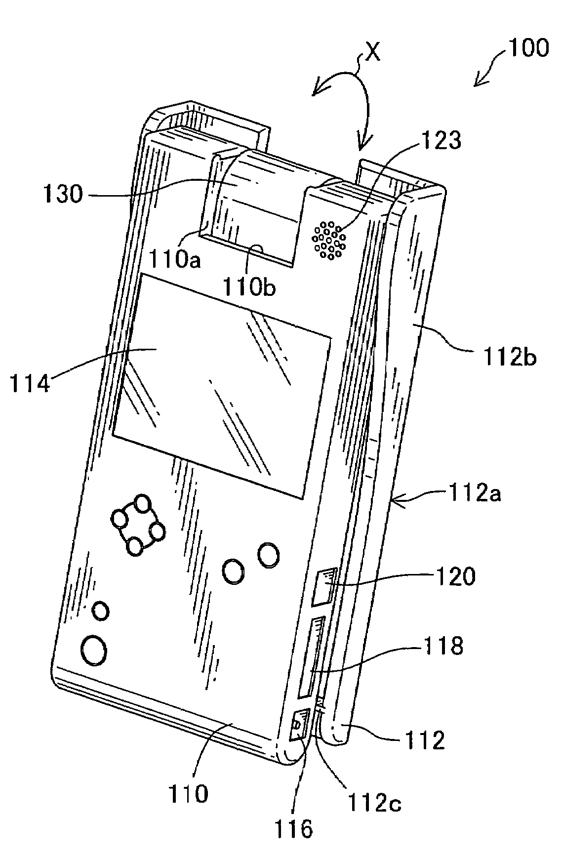
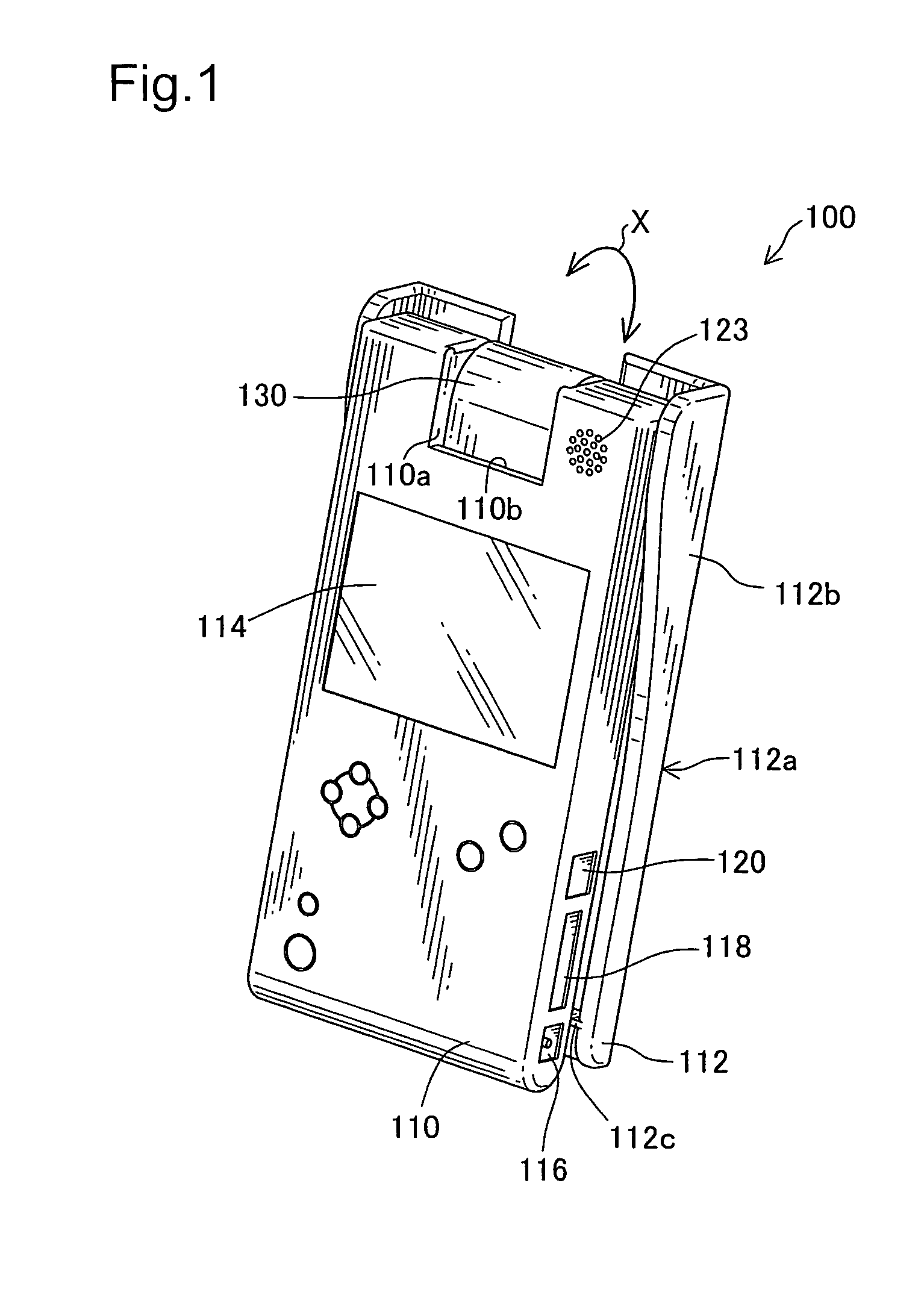
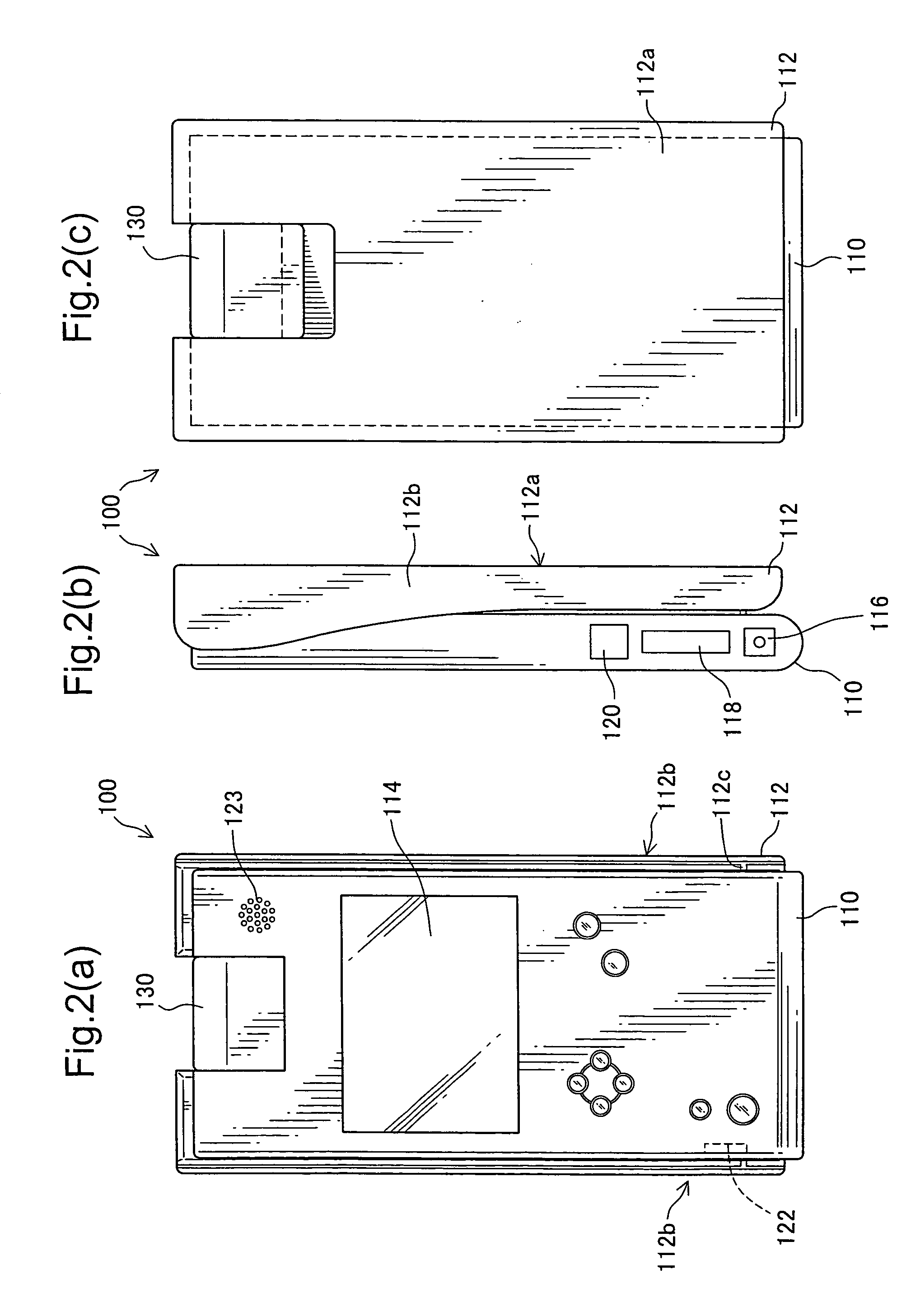
[0039]The following describes embodiments of the present invention. FIG. 1 is a perspective view schematically illustrating an imaging apparatus 100 with its lid closed; FIG. 2 is a schematic diagram illustrating a front side, lateral side, and back side of the imaging apparatus 100 with its lid closed; FIG. 3 is a perspective view illustrating the state of the imaging apparatus 100 when imaging an object on a desktop; and FIG. 4 is a perspective view illustrating the state of the imaging apparatus 100 when imaging surroundings.

[0040]As shown in FIG. 1, the imaging apparatus 100 has portability, which is as large as a datebook, and includes a lid body 112 attached to a main body 110. The main body 110 is a hollow casing, and includes electronics devices described later embedded therein, and a liquid crystal display panel 114 and a variety of buttons on the side that is not covered by the lid body 112. The main body 110 also includes on one lateral side a power supply connector 116,...

second embodiment

[0096]The second embodiment described above enables the imaging unit 130 to be rotated in conjunction with the opening movement of the lid body 112 and to be directed toward the object H on the straddle region MR at the completion of the opening of the lid body 112. That is, changing the attitude of the lid body 112 leads to setting the direction of the imaging unit 130. Therefore, when imaging the object on the straddle region MR, it is only required to open the lid body 112 into the predetermined position, and thereby facilitating the handling.

[0097]The following describes a modification. FIG. 19 is a schematic diagram illustrating a side view of an imaging apparatus 100 according to the modification; FIG. 20 is a schematic diagram illustrating the imaging apparatus 100 according the modification from the back side of the lid body 112; and FIG. 21 is a schematic diagram illustrating a plate 113a included in the lid body 112.

[0098]As shown, the lid body 112 includes an opening and ...


PUM


Abstract

An imaging apparatus that outputs an image of an object taken by an imaging device to an external display device is disclosed. The imaging apparatus includes a main body, a lid serving as a leg to support the main body, and electronics devices such as a controller within the main body. The lid is rotatably engaged with one end of the main body. In a first configuration, the lid overlaps the main body, and in a second configuration the lid and the main body form a V-shape, such that one end of the lid is separated from the main body. In the second configuration, the main body stands tilted and is supported by the lid, such that they straddle a top surface of the object supporter such as desktop. The imaging unit may thus be pointed toward the object located in the straddled region.

Description

BACKGROUND OF THE INVENTION[0001]The present invention relates to an imaging apparatus that includes an imaging device for imaging an object and outputs an image taken by the imaging device as an image signal to an external display device.DESCRIPTION OF THE RELATED ART[0002]Since such an imaging apparatus can display the image on a TV display etc, which has a large screen, a variety of imaging apparatuses have been proposed (e.g. JAPANESE PATENT LAID-OPEN GAZETTE No. 8-84294)[0003]The imaging apparatus facilitates taking an image of an object such as photograph located on a top surface of a table and the like, but the main body of the apparatus must be lifted up by use of left and right arms when imaging the object in this manner. Since this makes the center of gravity of the apparatus relatively higher, the apparatus does not have good stability, and thus there is still room for improvement. In addition, the left and right arms must be opened, and therefore there is also room for i...

Claims


Application Information

Patent Timeline
Patent Type & Authority Patents(United States)
IPC IPC(8): H04N5/225G03B17/02G03B17/04G03B17/56H04N1/04H04N5/222H04N5/253
CPCH04N5/2252H04N5/2253H04N23/51H04N23/54
Inventor YAMAKOSE, HIROSHI
Owner ELMO CO LTD
Why Eureka
Try Eureka