Compensating fiber for cumulated chromatic dispersion and chromatic dispersion slope

a technology of cumulated chromatic dispersion and fiber, applied in the field of optical fiber transmission, can solve the problems of reducing the error rate at the receiver, ssmf causing high losses with respect to the quantity of dispersion produced, and not being adapted for offsetting

Inactive Publication Date: 2008-10-21
DRAKA COMTEQ BV
View PDF10 Cites 32 Cited by
  • Summary
  • Abstract
  • Description
  • Claims
  • Application Information

AI Technical Summary

Problems solved by technology

It has also been found that overcompensation of chromatic dispersion reduces the error rate at the receivers.
The major drawback with the use of a SSMF section to offset over-compensation is that SSMF induces high losses with respect to the quantity of dispersion produced.
PSCF fibers induce fewer optical losses and have a FOM value in the order of 125 ps / nm / dB, but they are costly.
The fiber described in U.S. Pat. No. 2003 / 0202761 is therefore not adapted for offsetting overcompensation of a line section having negative cumulated chromatic dispersion and negative chromatic dispersion slope.

Method used


Image

  • Compensating fiber for cumulated chromatic dispersion and chromatic dispersion slope
  • Compensating fiber for cumulated chromatic dispersion and chromatic dispersion slope
  • Compensating fiber for cumulated chromatic dispersion and chromatic dispersion slope

Examples


Embodiment Construction

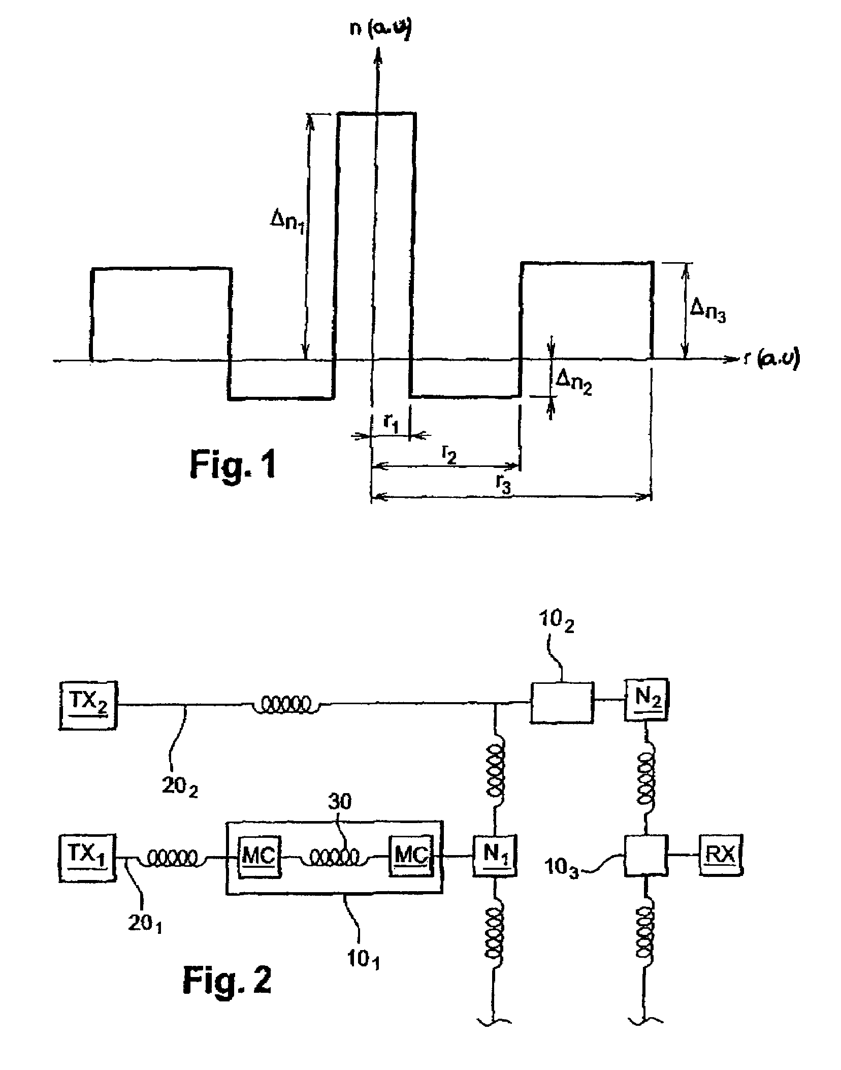
[0048]To offset the overcompensation of cumulated chromatic dispersion and chromatic dispersion slope in an optical transmission line section without incurring high losses, the invention proposes the use of a multimode compensating optical fiber having a particular index profile. Since overcompensation leads to negative cumulated chromatic dispersion and negative cumulated chromatic dispersion slope at the end of the line, the inventive fiber, for a high order mode, exhibits positive chromatic dispersion and positive chromatic dispersion slope with a Figure of Merit of more than 200 ps / nm / dB.

[0049]The fact that the dispersion compensating fiber is used in a transmission mode other than the fundamental mode, makes it possible for the fiber, at the wavelengths under consideration, to exhibit positive chromatic dispersion and positive chromatic dispersion slope with a high Figure of Merit.

[0050]FIG. 1 illustrates an index profile for a dispersion compensating fiber of the invention. Th...


PUM


Abstract

A multimode fiber having an index profile such that, for a propagation mode other than the fundamental mode and at a wavelength of 1550 nm, the fiber presents a positive chromatic dispersion greater than or equal to 50 ps / run / km, a positive chromatic dispersion slope and a figure of merit (FOM) greater than or equal to 200 ps / run / dB.

Description

BACKGROUND OF THE INVENTION[0001]The present invention relates to the field of optical fiber transmission and more specifically to the compensation of cumulated chromatic dispersion and cumulated chromatic dispersion slope in optical fiber transmission systems.[0002]For optical fibers, the index profile is generally qualified in relation to the graph of the function which associates the refractive index with the fiber radius. Conventionally the distance r to the center of the fiber is shown along the abscissa and the refractive index difference with the index of the fiber cladding is shown along the ordinate axis. The index profile is therefore referred to as “step”, “trapezoidal” or “triangular” profile for graphs having the respective shapes of a step, trapezoid or triangle. These curves are generally representative of the theoretical or set profile of the fiber, the manufacturing stresses of the fiber possibly leading to a substantially different profile.[0003]An optical fiber co...

Claims


Application Information

Patent Timeline
Patent Type & Authority Patents(United States)
IPC IPC(8): G02B6/00H04B10/2581
CPCG02B6/02019G02B6/02023G02B6/02266G02B6/0228G02B6/03644G02B6/03666G02B6/03688G02B6/29377H04B10/2581
Inventor ANTONA, JEAN-CHRISTOPHESILLARD, PIERRE
Owner DRAKA COMTEQ BV
Why Eureka
Try Eureka