
AFM cantilevers and methods for making and using same

a scanning probe microscope, high-performance technology, applied in the direction of mechanical roughness/irregularity measurement, instruments, etc., can solve the problems of low frequency to be useful in most biological applications, low design efficiency, and poor detection sensitivity of cantilevers, etc., to achieve high performance

Inactive Publication Date: 2008-10-28
THE JOHN HOPKINS UNIV SCHOOL OF MEDICINE
View PDF18 Cites 11 Cited by
  • Summary
  • Abstract
  • Description
  • Claims
  • Application Information

AI Technical Summary

Problems solved by technology

One of the limiting elements in current AFMs is the design of the cantilever.
This frequency is too low to be useful in most biological applications.
However, these types of cantilevers have relatively poor detection sensitivity and are difficult to work with in solution, preventing them from being used productively in biological research.
However, improvements in these cantilevers are largely limited by the lithographic and thin film deposition methods used for their fabrication.

Method used


Image

  • AFM cantilevers and methods for making and using same
  • AFM cantilevers and methods for making and using same
  • AFM cantilevers and methods for making and using same

Examples


example 1

FIB Generated Cantilever

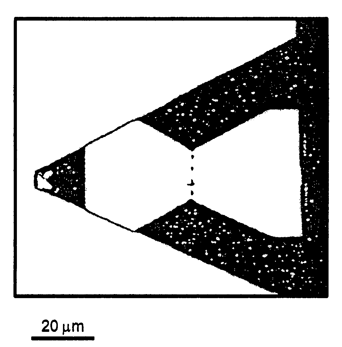
[0120]To make rectangular cantilevers, a starting material comprising a straight beam-shaped B Microlever with a nominal resonant frequency of 15 kHz in air and a nominal force constant of 0.02 N / m. After milling, the resonant frequency of one of the cantilevers provided in this way (cantilever 1) in air increased to 126 kHz, and in water the resonant frequency increased from 3.5 kHz to 51 kHz (Table 2). In both cases, there is a peak centered at zero frequency due to 1 / f and other electronic noise. The force constant increased to 0.20 N / m.

[0121]The resonant frequency of a cantilever 2 produced by this method was increased by a similar amount, i.e., to 106 kHz in air and 42 kHz in water. The small difference between cantilevers 1 and 2 is probably due to the slightly longer legs of cantilever 2. Note that the ratio ωs / ωv improved in the modified cantilevers, and is ˜0.4 compared with 0.25-0.3 for unmodified cantilevers.

[0122]To make a V-shaped cantilever (can...

example 2

Generation of Cantilevers by Electron Beam Deposition

[0132]High performance cantilevers were grown on the end of conventional silicon nitride cantilevers or near the apex of high force constant Si-cantilevers. The silicon nitride cantilevers were V-shaped and 83 μm from based to free end, with a nominal force constant of 0.5 N / m. The Si-cantilevers were straight beams 125 um long with a force constant of 10-50 N / m. The cantilevers were mounted on a standard scanning electron microscope (SEM) mount, with the cantilever pointing toward the electron beam. An Amray 1810 SEMI equipped with a tungsten filament source was used. The microscope was operated at 30 kV using a condenser lens setting of 14, at 40,000 to 60,000× magnification and working distance of ˜10 mm.

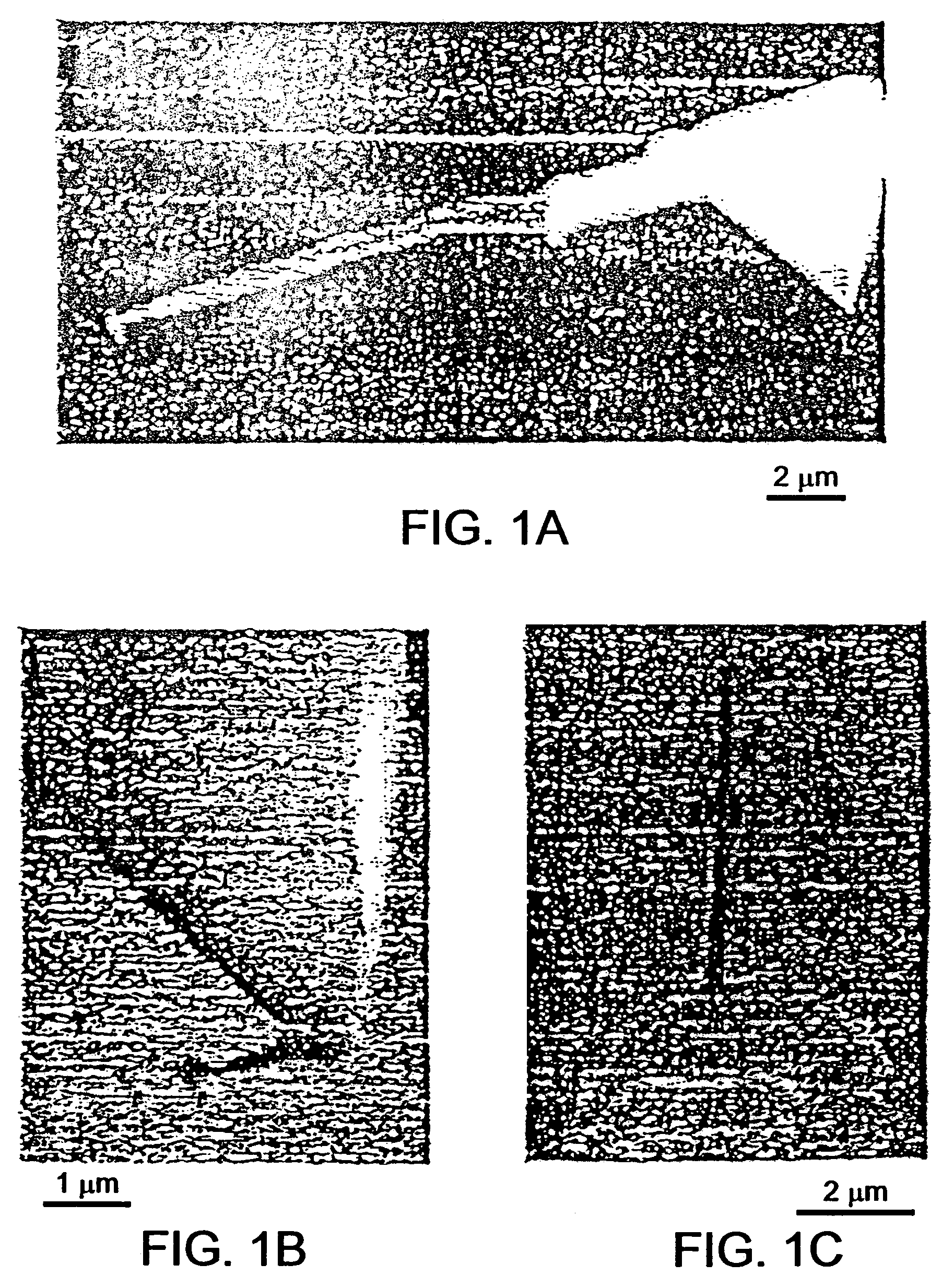
[0133]Electron beam deposited cantilevers up to 12 μm in length were constructed, with the only obvious limit being patience of the SEM operator (FIG. 1A). On a standard SEM, the mechanical drift in the system required adjustme...


PUM

PropertyMeasurementUnit
thicknessaaaaaaaaaa
resonant frequencyaaaaaaaaaa

Abstract

The invention provides high performance cantilevers with optimal combinations of high resonant frequency and low force constant. In one aspect, AFM cantilevers with spring constants in the range 1-10−6 N / m with (fundamental) resonant frequencies in aqueous solutions of 0.1-100 MHz are provided. A high performance cantilever may be made by focused ion beam milling or electron deposition. The high performance cantilevers allow faster scanning, increase the temporal resolution of force measurement, improve measurement sensitivity by reducing cantilever noise, and improve sensitivity by reducing cantilever spring constant.

Description

RELATED APPLICATIONS[0001]This application claims priority under 35 U.S.C. § 119(e) to U.S. Provisional Application 60 / 280,267, filed Mar. 30, 2001 and to U.S. Provisional Application No. 60 / 314,235, filed Aug. 22, 2001, the entireties of which are incorporated by reference herein.FIELD OF THE INVENTION[0002]The invention relates to high performance cantilevers for scanning probe microscopes, such as Atomic Force Microscopes, and to methods of making and using the same.BACKGROUND OF THE INVENTION[0003]Scanning probe microscopes (SPMs) obtain data regarding surface topography by using a sharp tip or probe on the end of a cantilever held on or at a short distance (e.g., about 5-500 Å) from a sample. The cantilever tip can be deflected by various forces acting at the interface between the sample and the tip, such as electrostatic, magnetic, and van der Waals forces. A movement of the cantilever due to interactions between an atom at the end of the tip and an atom of the sample can then...

Claims


Application Information

Patent Timeline
Patent Type & Authority Patents(United States)
IPC IPC(8): G12B21/00G01N13/10G01Q60/40G01Q70/12G01Q70/14G01Q70/16
CPCG01Q60/38B82Y35/00
Inventor HOH, JAN H.
Owner THE JOHN HOPKINS UNIV SCHOOL OF MEDICINE
Learn More