
Moving device in pipe lines

a moving device and pipe line technology, applied in the direction of instruments, wellbore/well accessories, ways, etc., can solve the problems of cumbersome operation to block up the vibrating traveling legs, cumbersome operation to change the position of the covers, balloons and bellows take a long time for injection/exhaustion, etc., and achieve the effect of being easily moved

Inactive Publication Date: 2008-10-28
NIPPON CABLE SYSTEM INC
View PDF10 Cites 32 Cited by
  • Summary
  • Abstract
  • Description
  • Claims
  • Application Information

AI Technical Summary

Benefits of technology

[0012]This invention is directed to provide a moving device in pipe lines that allows easy switching of moving / stopping, remote control of moving / stopping by only electrical wires, and further, easy operation in small diameter pipe lines.
[0052]In the case that a storage in which movement patterns of the segment and a controlling part which controls the movement of segments according to movement patterns of segments are provided (Claim 20), since a segment can be moved according to a engaging force inside pipe lines, the segment can be easily moved in various shaped pipe lines.

Problems solved by technology

However, it is necessary to let through the guide wide previously requiring cumbersome insertion of the guide wire and the reinsertion of the guide wire in the cases of path changes.
However, it is a cumbersome operation to block up the vibrating traveling legs with the covers, particularly it is a more cumbersome operation to change the position of the covers.
However, the balloons and the bellows take much time for injection / exhaust of air or liquid, and they require to secure pipe lines requiring a cumbersome operation.
Further, any of them can not be manufactured in reduced size, therefore, no actual unit for small diameter tubular organs or pipe lines has not yet been put to practical use.

Method used


Image

  • Moving device in pipe lines
  • Moving device in pipe lines
  • Moving device in pipe lines

Examples


second embodiment

[0097]The rough control block diagram of the moving device in the second embodiment in FIG. 5a is shown. In FIG. 5a, the plural electromagnets (moving part 40) in the moving device 30 which move forward and backward in the pipe lines and the controller 41 which outputs the instructions to move to the moving part 40 are shown in a simplified figure. The above three moving part 40 are almost the same, but they are so designated that the one connected to the controller 41 is the end moving part 40, the one placed at the front edge is the front edge moving part 40, and the remaining one placed between the front edge and the end edge is the medium moving part 40. The moving device 30 comprises three moving part 40, but it can be extended by increasing the medium moving part 40.

[0098]The each moving part 40 is provided with a mechanical part 42 driving the each moving part 40 and a driver 43 controlling the mechanical part 42. The above mechanical part 42 corresponds to the coil provided ...

third embodiment

[0112]As the mechanical part 42, those operated by the variation of the poles are described above. Subsequently, the device which is operated by extending or retracting the mutual spacing in between the moving part 40 using an extendable part is described. Thereinafter, the moving device employing such extendable part is described.

[0113]The moving device 60 shown in FIG. 6a is composed of four segments (the moving part 40) that are a segment A, a segment B, a segment C, and a segment D starting from the left. These segments are interconnected linearly and slidably by an extendable part 74 (extendable connecting means). The above extendable part 74 corresponds to the mechanical part 42 in FIG. 5a. In this figure, the mutual contacting part of the segments shows the retracted condition of the extendable part 74, and the extended condition is shown by the crossbar. To the rear segment D is connected an electric wire 64 to supply power for extending the extendable part 74 or a communica...


PUM


Abstract

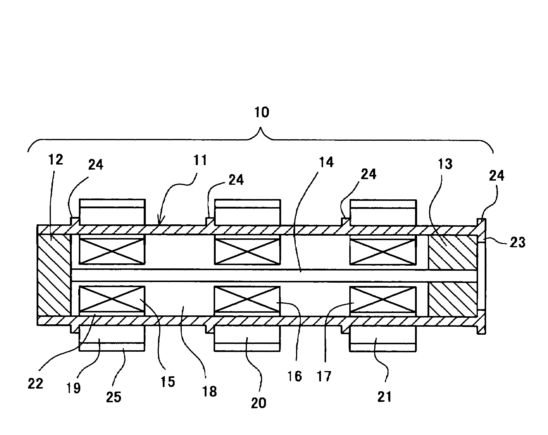
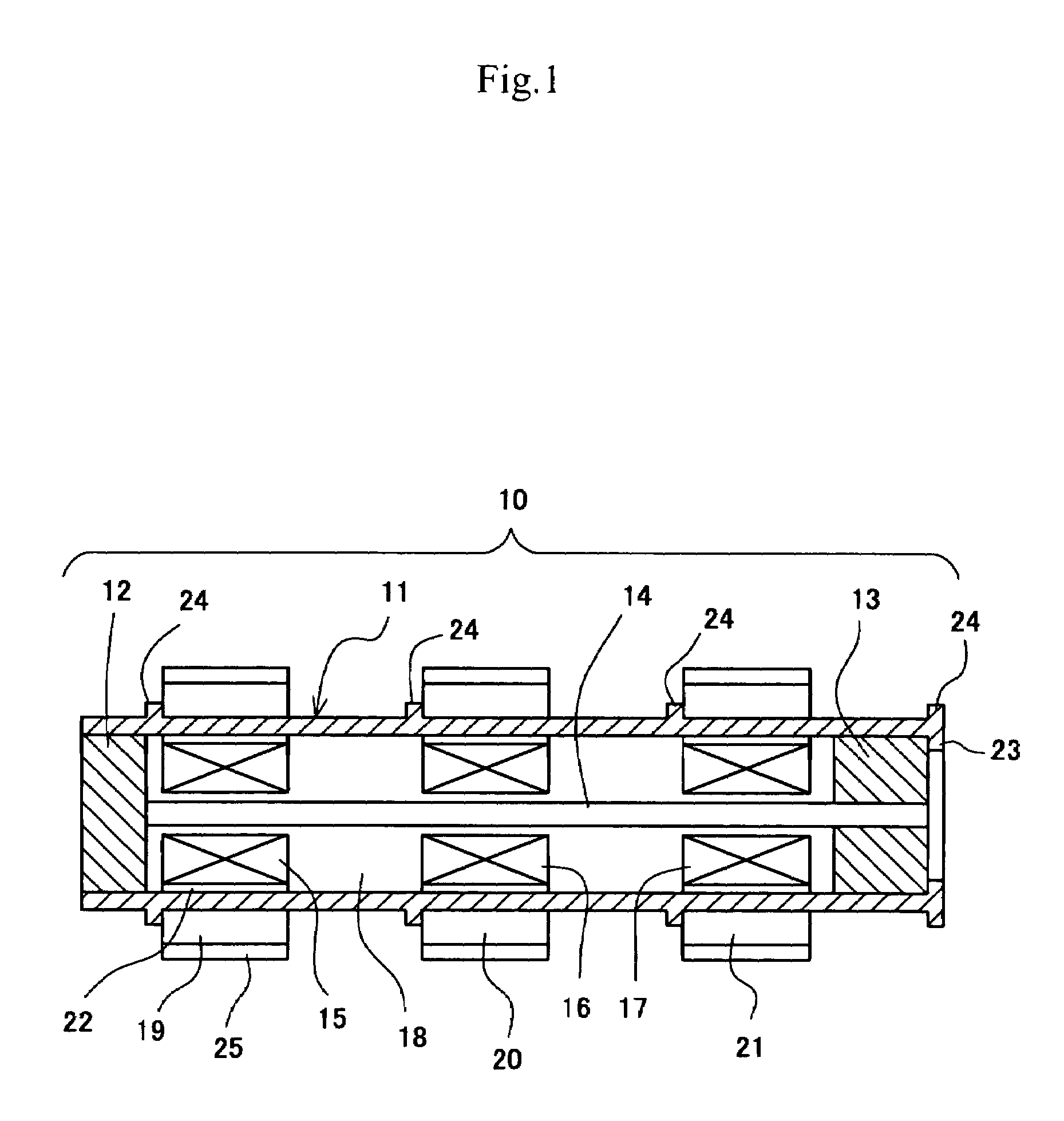
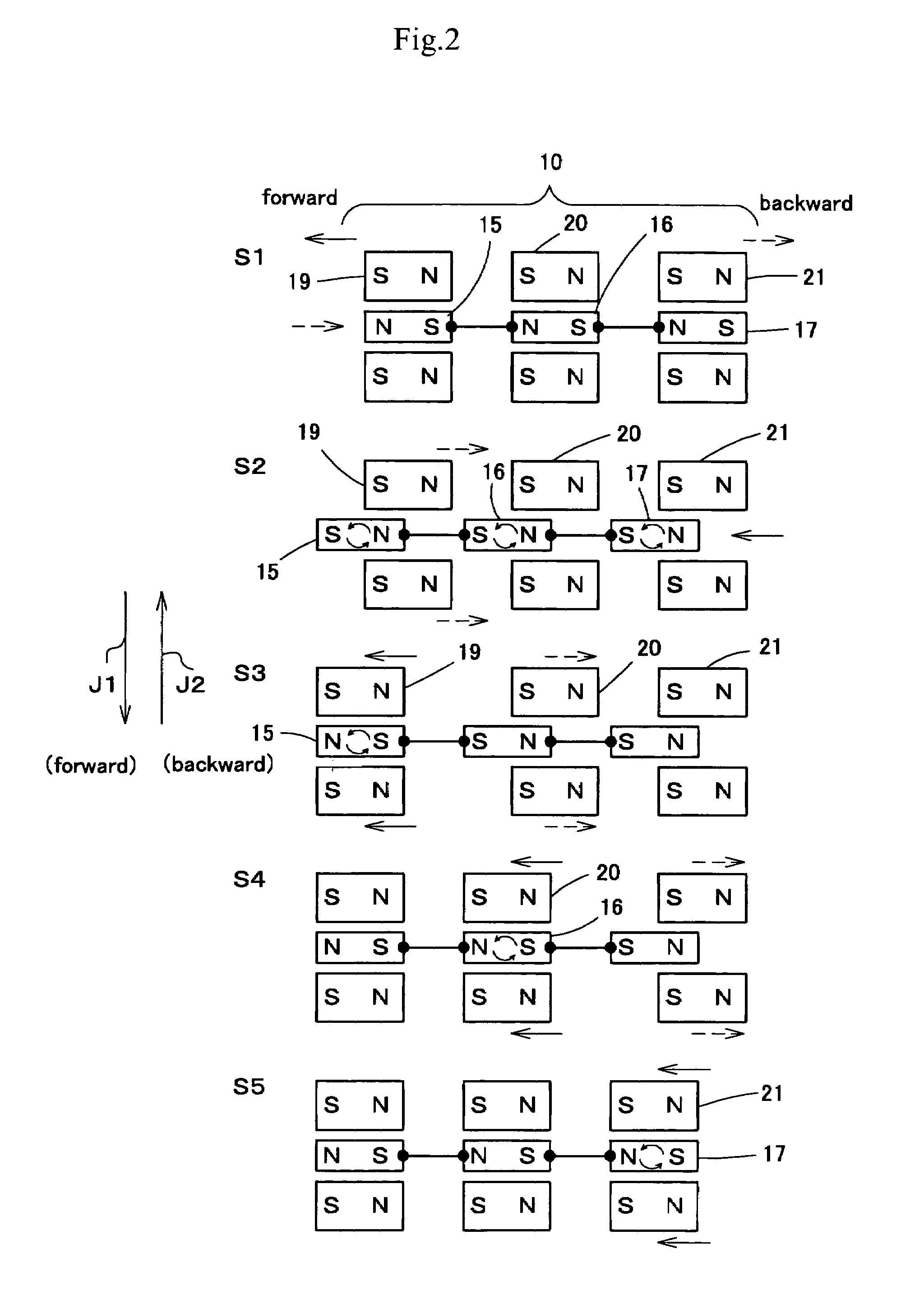
A moving device in pipe lines is provided, which allows easy switching of moving / stopping and remote control of the switching by only electric wires enabling easy operation in the inside of small diameter pipe lines.The moving device 10 in pipe lines comprises a guide frame 11 in which a line of three or more coils 15, 16, 17 is interconnected flexibly in the direction of magnet flux, ring-shaped permanent magnets 19, 20, 21 provided around the periphery of the guide frame slidably in the direction of the shaft, and a control means such as computers etc. to control by a preset program selecting the direction of turning on of the coils.

Description

FIELD OF THE INVENTION[0001]This invention relates to a moving device in pipe lines, and more particularly to a moving device in pipe lines which moves / stops by being remote controlled or autonomously in body cavities or in pipe lines used for carrying various sensors to affected parts or to parts to be repaired, or for carrying and discharging medical agents such as curative medicines or mending agent for the part to be repaired.BACKGROUND ARTS[0002]Patent Document 1: Japanese Patent Laid Open No.1994-114037[0003]Patent Document 2: Japanese Patent Laid Open No.1993-212093[0004]Patent Document 3: Japanese Patent Laid Open No.1995-289504[0005]In the Patent Document 1, a medical capsule which has plural capsules running along one guide wire inserted into a body cavity is disclosed. This is provided with a roller to tuck the guide wire in the capsule and a micro motor to drive the roller. The driven roller runs the capsule by the reactive force obtained from the guide wire. Further in ...

Claims


Application Information

Patent Timeline
Patent Type & Authority Patents(United States)
IPC IPC(8): B61B13/10B60L13/04A61B1/005G01B7/16
CPCA61B1/00156A61B1/00158A61B1/0055B08B9/049E21B23/14F16L55/28F16L55/34H02K57/006A61B2019/2253A61B34/73H02K99/20
Inventor TERAURA, MAKOTOSUZUKI, KAZUHIRO
Owner NIPPON CABLE SYSTEM INC
Learn More