Wire manufacturing method wire manufacturing apparatus and wire

a manufacturing method and wire technology, applied in the direction of insulated conductors, cables, conductors, etc., can solve the problems of reducing the material yield of electric wires, reducing the manufacturing efficiency of electric wires, and difficulty in changing the color agent from a dark coloring agent to a bright coloring agen

Inactive Publication Date: 2008-10-28
YAZAKI CORP
View PDF37 Cites 25 Cited by
  • Summary
  • Abstract
  • Description
  • Claims
  • Application Information

AI Technical Summary

Benefits of technology

[0023]In this configuration, the extrusion cladding step of forming the cladding and the coloring step of coloring the electric wire are implemented individually. Therefore, by changing the color in the coloring step, the color applied to the electric wire can be easily changed. In the extrusion cladding step, the cladding is coated with the non-color synthetic resin. Therefore, the product numbers (kinds of the color of the outer surface) of the electric wire which is obtained by extrusion cladding can be reduced. In the coloring step, the outer surface of the non-colored cladding is colored. Therefore, even when the outer surface of the non-colored cladding is colored with the color having higher brightness than that of the outer surface, the non-colored resin can be hidden by the color adopted in the coloring step.
[0066]In this configuration, the upstream coloring portion of the coloring portions is operated while a downstream coloring portion thereof is being operated, and the downstream coloring portion is stopped after the electric wire moves over an interval between the coloring portions. Therefore, when the coloring portions are exchanged, any overlapping portion of the first color and the second color can be avoided and the area not colored with both colors can be avoided. Thus, the boundary between the first area colored with the first color and the second area colored with the second color can be clarified.

Problems solved by technology

This reduced the manufacturing efficiency of the electric wires 106.
This led to a tendency of decreasing the of material yield of the electric wire 106.
This made it difficult to change the color agent from a dark coloring agent to a bright coloring agent.
Thus, the technique described in JP-A-6-150774 has a limitation in changing the coloring agent that the coloring agent must be changed into the coloring agent with lower brightness.
Therefore, a large space is required to store the electric wires and a troublesome work is necessary to manage the product numbers of the electric wires 106.

Method used


Image

  • Wire manufacturing method wire manufacturing apparatus and wire
  • Wire manufacturing method wire manufacturing apparatus and wire
  • Wire manufacturing method wire manufacturing apparatus and wire

Examples


Embodiment Construction

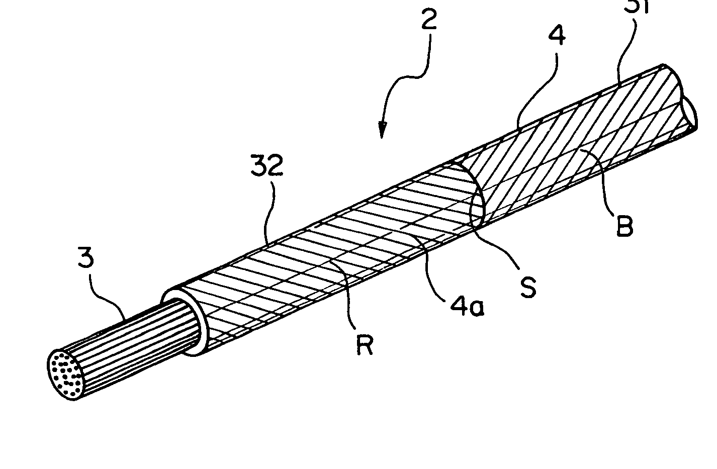
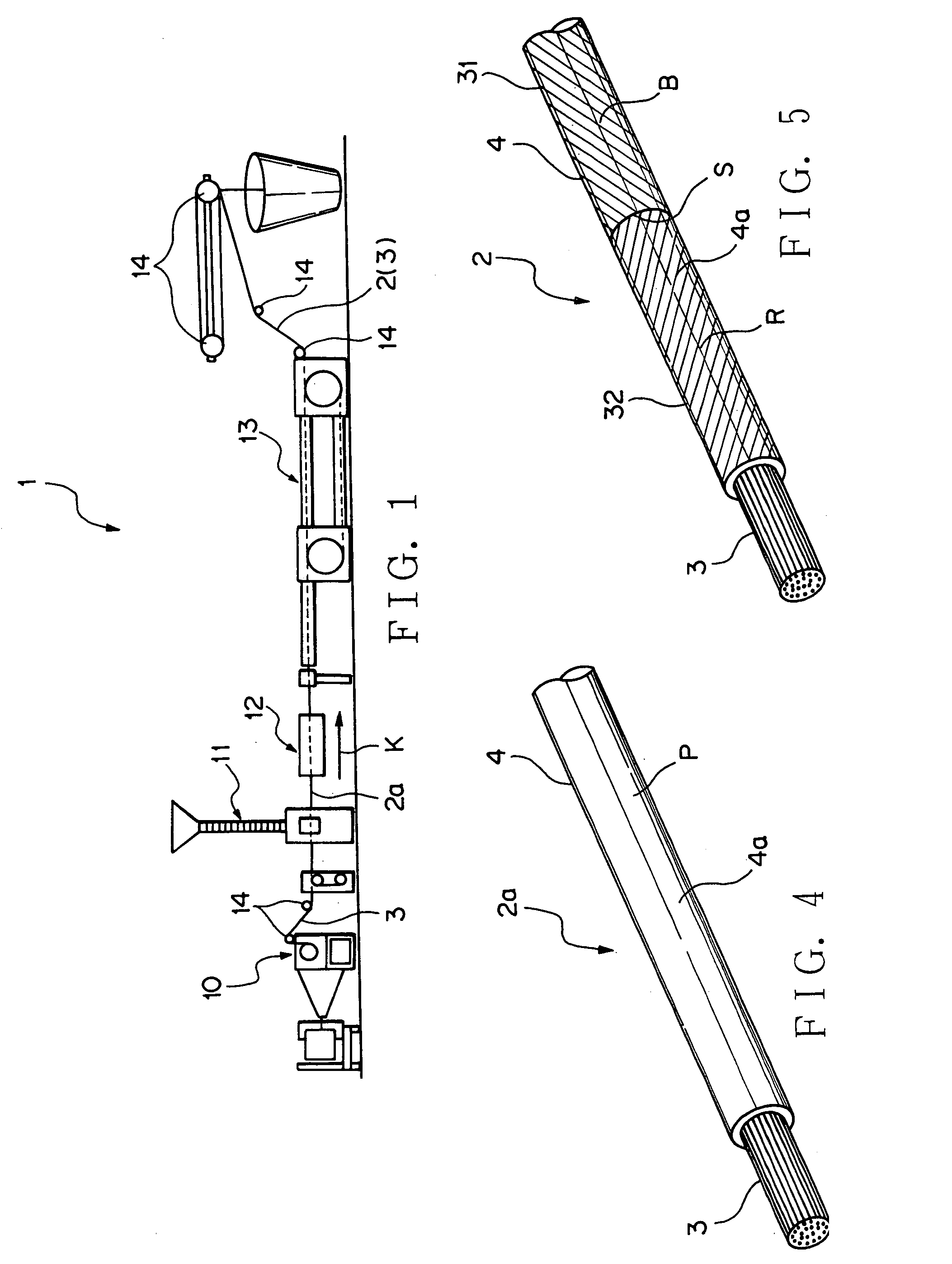
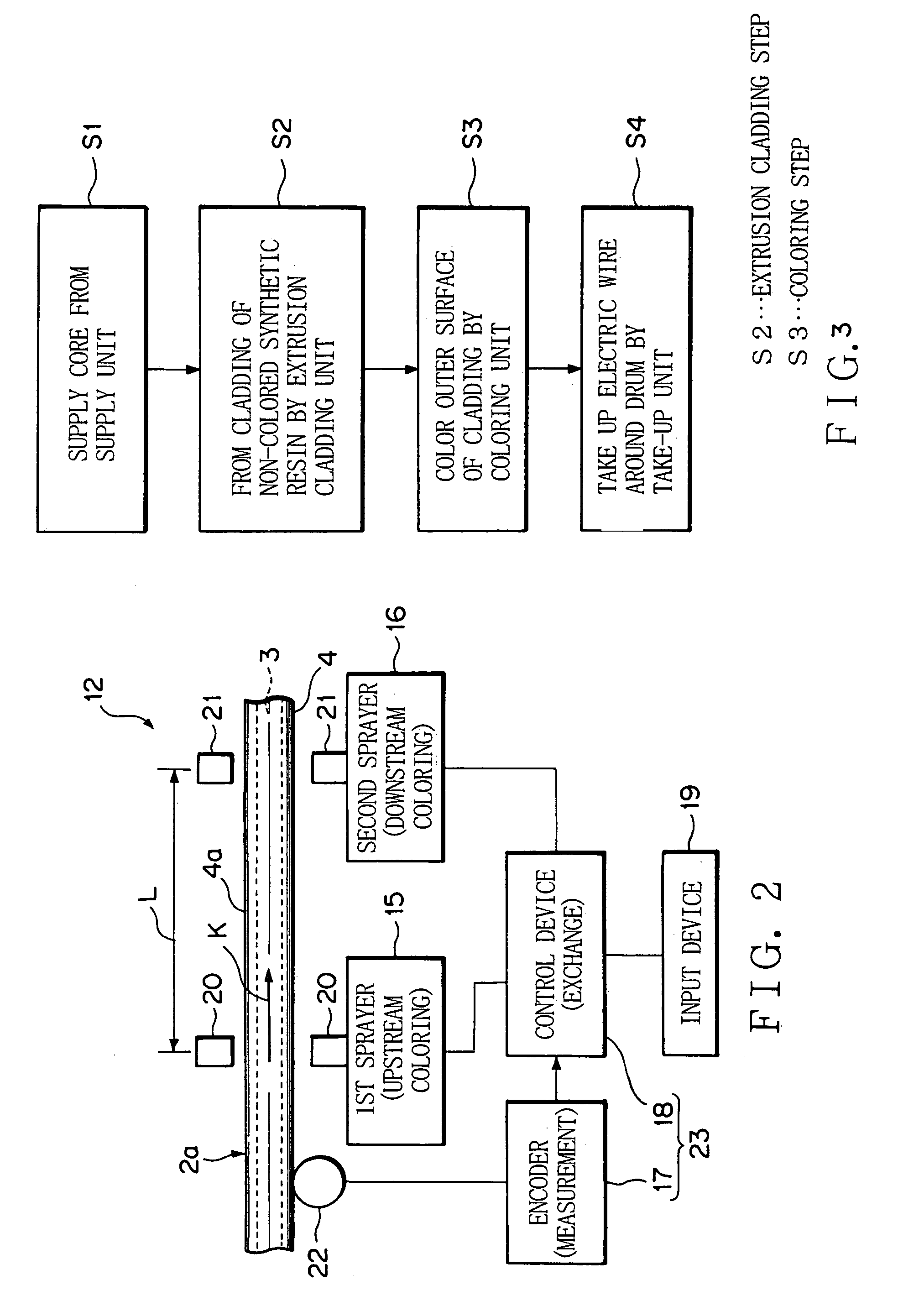
[0077]Now referring to FIGS. 1 to 9, an explanation will be given of a method and apparatus for manufacturing an electric wire according to an embodiment of this invention. An electric wire manufacturing apparatus shown in FIG. 1 according to an embodiment of this invention is an apparatus which once manufactures a non-colored electric wire 2a as shown in FIG. 4 and colors the non-colored wire 2a to manufacture an electric wire 2 as shown in FIG. 5. Incidentally, since these electric wires 2 and 2a have the same construction, their like portions are designated by like reference numerals.

[0078]The electric wire 2 constitutes the wire harness of the moving body such as a motor vehicle. The electric wire 2, 2a, as shown in FIGS. 4 and 5, is composed of a conductive core 3 and insulating cladding 4. The core 3 is composed of a plurality of twisted strands. The strand is made of conductive metal. The core 3 may be composed of a single strand. The cladding 4 is made of synthetic resin suc...


PUM

PropertyMeasurementUnit
electricaaaaaaaaaa
coloraaaaaaaaaa
moving distanceaaaaaaaaaa

Abstract

This invention intends to provide a method and apparatus for manufacturing an electric wire, capable of easily changing a color applied to the electric wire. The electric wire manufacturing apparatus intends to manufacture an electric wire composed of a core and a cladding. In step S1, the core is supplied from a supply unit. In step S2, in an extrusion cladding unit, the outer periphery of the core is coated with non-color synthetic resin by extrusion cladding to form the cladding. In step S3, the outer surface of the cladding is colored by a coloring unit. The coloring unit includes a plurality of sprayers 15 and 16. In step S3, the sprayers 15 and 16 are exchanged to operate as necessary. In step S4, in a take-up unit, the electric wire is cut into segments each having a desired length, which are wound around a drum.

Description

TECHNICAL FIELD[0001]This invention relates to a method and apparatus for manufacturing an electric wire composed of an electric core and an insulating cladding which clads the core, and the electric wire itself.BACKGROUND ART[0002]A moving body such as a motor vehicle is equipped with various electronic devices. Therefore, in order to supply electric power from a power source and a control signal from a computer to these electronic devices, a wire harness 100 is arranged in the motor vehicle. The wire harness includes plural electric wires 106 (FIG. 10) and connectors attached to the ends thereof.[0003]The electric wire 106 is composed of a conductive core 105 (FIG. 10) and a cladding which is made of insulating synthetic resin and clads the core 105. The electric wire 106 is a “clad-wire”. The electric wire 106 has been manufactured by a manufacturing apparatus 100 shown in FIG. 10. The manufacturing device illustrated in FIG. 10 includes a supply unit 101, an extrusion cladding u...

Claims


Application Information

Patent Timeline
Patent Type & Authority Patents(United States)
IPC IPC(8): H01B7/00H01B7/36H01B13/34
CPCH01B13/345
Inventor KAMATA, TEKESHISUZUKI, SHIGEHARUSUGIMURA, KEIGOYAGI, KIYOSHI
Owner YAZAKI CORP
Why Eureka
Try Eureka