Spectrophotometric scanner

a spectrophotometric and scanner technology, applied in the field of spectrophotometric scanners, can solve the problem of difficult to precisely determine the reflection of spectral energy by using a single spectrophotometer measuremen

Inactive Publication Date: 2008-10-28
VIE GRP
View PDF23 Cites 50 Cited by
  • Summary
  • Abstract
  • Description
  • Claims
  • Application Information

AI Technical Summary

Benefits of technology

[0008]In one exemplary embodiment, the first light director is a light pipe formed such that light entering a short face of the light pipe is radiated uniformly along a longer face of the light pipe. In this exemplary embodiment, the reference detector is a photodiode. The light source is a plurality of sequentially controllable LEDs, each producing light in a different wavelength band. Depending on implementation, the different wavelength bands include the ultraviolet, visible, and infrared regions of the electromagnetic spectrum. In this exemplary embodiment the row of light sensing elements are a row of charge coupled devices (CCDs). Alternatively, the row of light sensing elements may be a row of Active Pixel Sensors (APSs).
[0009]Scanning may be accomplished by moving the scanner head while maintaining the sample fixed or by moving the sample while maintaining the scanner head fixed.

Problems solved by technology

Hence, it is difficult to use a single spectrophotometer measurement to precisely determine how reflected spectral energy varies over a particular surface area.

Method used


Image

  • Spectrophotometric scanner
  • Spectrophotometric scanner
  • Spectrophotometric scanner

Examples


Embodiment Construction

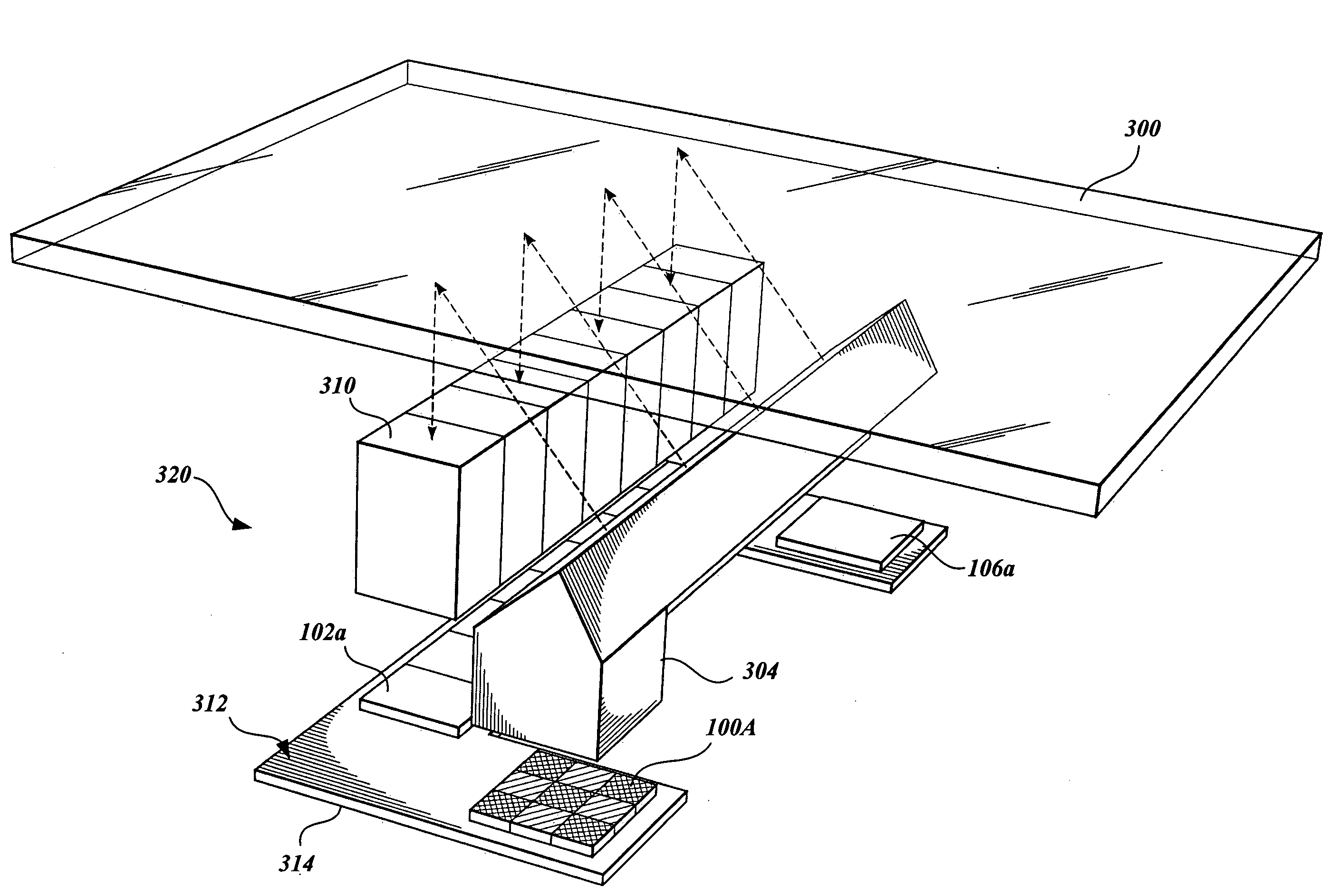
[0025]The spectral energy reflected from a surface (“spectral reflectance”), such as the surface of printed matter, textile, molded or machined part, etc., often varies in intensity and / or wavelength from one location to another across the surface. The distances between locations may be small, e.g., less than a millimeter. Typical spectrophotometers provide one integrated measurement of a surface area with a diameter of roughly 4 mm to 24 mm. Such integrated measurements are described by the following equation:

m(λ)=∫(x,y)εAr(λ,x,y)dxdy λ=400, 410, . . . , 690, 700 nm  (1)

In equation (1), m(λ) is a spectrophotometer measurement for wavelength λ; A is the spectrophotometer aperture size; and r(λ,x,y) is the spectral reflectance of the surface at spatial location x and y for wavelength λ. Spectrophotometer measurements are unable to distinguish variations in surface spectral reflectance intensity that are less than about 4 mm apart. In addition, in a single capture, traditional spectro...


PUM

PropertyMeasurementUnit
angleaaaaaaaaaa
angleaaaaaaaaaa
diameteraaaaaaaaaa

Abstract

A spectrophotometric scanner suitable for producing spectral reflectance images of surfaces of samples for a plurality of wavelength bands is disclosed. The spectrophotometric scanner comprises a scanner head for collecting spectral reflectance data, a positioning mechanism for positioning the scanner head in relation to a surface, and a computing device for controlling the mechanism and recording and analyzing the spectral reflectance data. The computing device directs the positioning mechanism to position the scanner head on a row of locations in a grid of locations of the surface; directs the scanner head to measure spectral reflectance data for each location in the row of locations; records and analyzes the spectral reflectance data; and produces spectral reflectance images from the spectral reflectance data. A light source in the scanner head comprises a plurality of sequentially controllable LEDs, each producing light in a different wavelength band.

Description

CROSS-REFERENCE TO RELATED APPLICATION[0001]This application claims the benefit of U.S. Provisional Patent Applications No. 60 / 682,304, filed May 18, 2005, and No. 60 / 682,305, filed May 18, 2005, the subject matter of which is also incorporated herein by reference.BACKGROUND[0002]Spectrometers are optical instruments used to measure electromagnetic radiation properties, e.g., light intensity, over a specific portion of the electromagnetic spectrum range from the infrared band to the gamma ray band. Normally, a particular spectrometer operates over a limited portion of this total range because different techniques are used to measure the energy in different portions of the electromagnetic spectrum. Spectrometers determine the distribution of spectral energy portions within the electromagnetic spectrum by measuring the intensity of radiation absorbed, reflected, or emitted by a material as a function of different wavelengths, separating the radiation measurements into energy bands, an...

Claims


Application Information

Patent Timeline
Patent Type & Authority Patents(United States)
IPC IPC(8): G01N21/27G01N21/47G02B26/10G01J3/50
CPCG01J3/10G01J3/2823G01J3/32G01J3/50G01J3/501G01J3/52G01J3/524G01N21/25G01N21/55G01J3/0262G01J3/027G01N21/274G01N21/8983G01N2201/0627G01N2201/101
Inventor VRHEL, MICHAEL JISELI, VICTOR L
Owner VIE GRP
Why Eureka
Try Eureka