Electrical connector with shell

a technology of electric connectors and metal shells, applied in the direction of coupling devices, two-part coupling devices, securing/insulating coupling contact members, etc., can solve the problems of loose position between metal shells and insulated housings, incontrollable, etc., and achieve the effect of complementary connector mating and improved structur

Active Publication Date: 2008-11-04
HON HAI PRECISION IND CO LTD
View PDF15 Cites 29 Cited by
  • Summary
  • Abstract
  • Description
  • Claims
  • Application Information

AI Technical Summary

Benefits of technology

[0007]Accordingly, an object of the present invention is to provide an electrical connector with improved structures to make a complementary connector mating with the electrical connector more easily and accurately.
[0008]Another object of present invention is to provide an electrical connector with improved structures to make it easy and convenient to assemble the electrical connector to a circuit substrate.

Problems solved by technology

When formed in 1990, the original goals were limited to define de facto mechanical envelopes within which disk drives can be developed to fit compact computer and other small products.
Thus, the position between the metal shell and the insulated housing is loose and incontrollable.

Method used


Image

  • Electrical connector with shell
  • Electrical connector with shell
  • Electrical connector with shell

Examples


Embodiment Construction

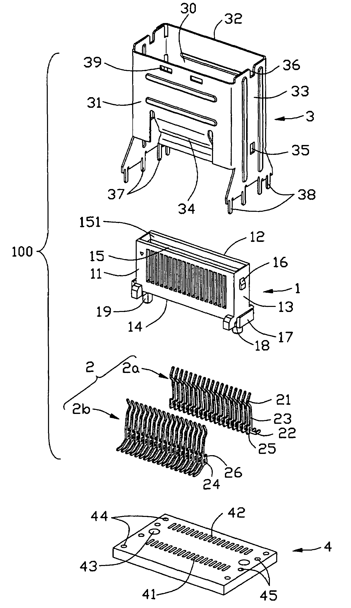
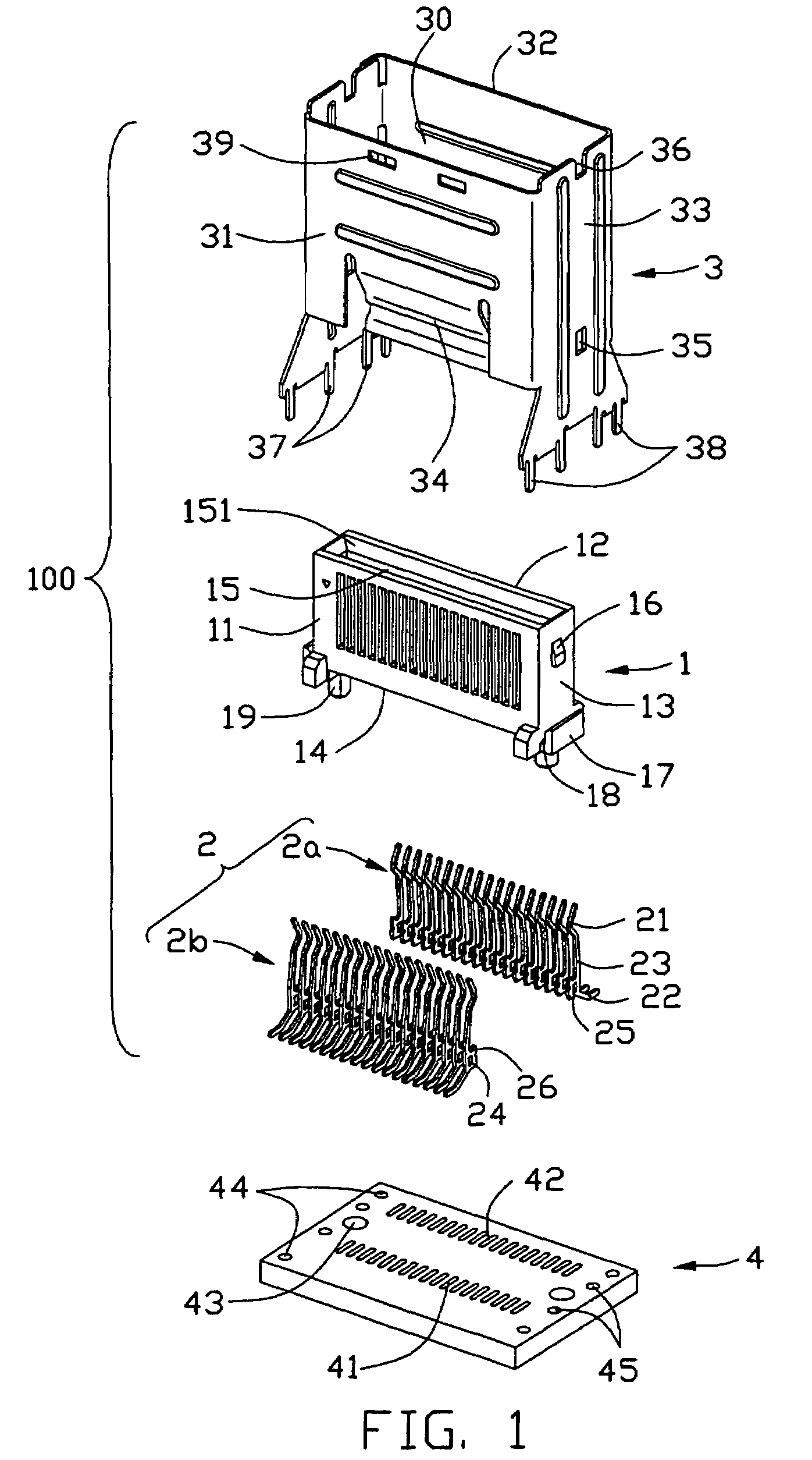
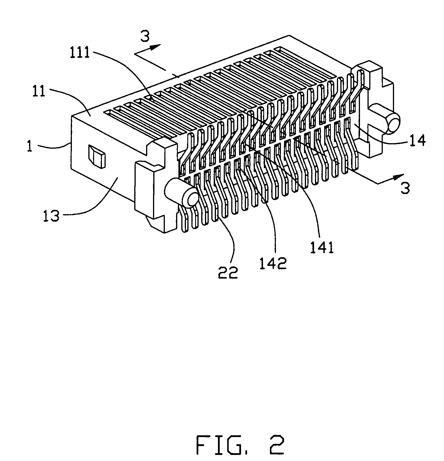
[0016]Reference will now be made in detail to the preferred embodiment of the present invention.

[0017]Referring to FIG. 5, a vertical-type electrical connector 100 mounted on a circuit substrate 4 for mating with a complementary connector 200. The complementary connector 200 comprises a substantially cubic body portion 201, a first protruding member 202 and a second protruding member 203 spaced apart from each other in a parallel relationship and respectively extending downwardly from the bottom portion of the body portion 201, a printed circuit board (PCB) 204 disposed between substantially middle of the first protruding member 202 and the second protruding member 203 with its upper portion received in the body portion 201, a plurality of cables 207 electrically connecting with conductive traces (not shown) of the PCB 204 with their connecting portions over-molded within upper portion of the body portion 201, and a latch mechanism 205 assembled on the front portion of the body port...


PUM


Abstract

An electrical connector (100) includes an insulated housing (1), a number of terminals (2) arranged into two rows and received in the insulated housing respectively and a metal shell (3) pre-assembled with the insulated housing via coupling device. The insulated housing (1) comprises a front wall, a back wall, a bottom wall and a pair of lateral walls interconnecting with the front, the back and the bottom walls to define a hollow. The metal shell (3) comprises a front side, a rear side and a pair of transversal sides joining to the front and the rear sides to define a receiving space (30). The lower section of the receiving space is used for housing the insulated housing and the upper section of the receiving space is adapted for receiving the complementary connector.

Description

CROSS-REFERENCE TO RELATED APPLICATION[0001]This application is related to U.S. patent application Ser. No. 11 / 492,148 filed on Jul. 24, 2006, invented by George (Huan Yi) Zhang, entitled “ELECTRICAL CONNECTOR WITH SHELL”, which is assigned to the same assignee as this application.BACKGROUND OF THE INVENTION[0002]1. Field of the Invention[0003]The present invention generally relates to an electrical connector, and more particularly to an electrical connector with a metal shell.[0004]2. Description of Related Art[0005]The SFF Committee is an ad hoc group formed to address storage industry needs in a prompt manner. When formed in 1990, the original goals were limited to define de facto mechanical envelopes within which disk drives can be developed to fit compact computer and other small products. A Mini SAS connector is one kind of high-speed I / O port established by the SFF Committee, and this kind of connector can transmit data up to 3 Gbps or more. Such Mini SAS receptacle connector...

Claims


Application Information

Patent Timeline
Patent Type & Authority Patents(United States)
IPC IPC(8): H01R13/648
CPCH01R13/6275H01R23/6873H01R12/707H01R12/57H01R12/58H01R13/506H01R13/6658H01R13/658
Inventor ZHANG, GEORGEHUANYI
Owner HON HAI PRECISION IND CO LTD
Why Eureka
Try Eureka