Evaporative emission control in battery powered vehicle with gasoline engine powered generator

a technology gasoline engine, which is applied in the direction of electric control, combustion air/fuel air treatment, machines/engines, etc., can solve the problems of diurnal vapor generation of conventional fuel tanks and no purging (cleaning) of evaporative emission control canisters, and achieve the effect of preventing canister fuel vapor bleed emissions

Inactive Publication Date: 2008-11-11
GM GLOBAL TECH OPERATIONS LLC
View PDF13 Cites 91 Cited by
  • Summary
  • Abstract
  • Description
  • Claims
  • Application Information

AI Technical Summary

Benefits of technology

[0007]In a representative embodiment of the invention, the solenoid valves (or other suitable valves) in both control lines are closed except during fuel tank refueling and engine operation. Thus, the fuel tank and its ORVR canister are sealed shut with respect to venting of fuel vapor except for canister purging during engine operation and subsequent fuel tank venting and canister loading during refueling of the vehicle. Diurnal fuel temperature and pressure fluctuations are contained by the sealed system with some canister loading during fuel temperature and tank pressure increases and some canister unloading to the tank during fuel temperature and pressure decreases. The pressure / vacuum relief valve and line accommodates abnormal fluctuations in fuel tank pressure or vacuum. Thus, fuel vapor is contained within this sealed plug-in hybrid fuel system preventing canister fuel vapor bleed emissions.

Problems solved by technology

A plug-in hybrid vehicle IC engine may not run for several days which results in no purging (cleaning) of the evaporative emission control canister.
However, a conventional fuel tank will be generating diurnal vapors everyday.

Method used


Image

  • Evaporative emission control in battery powered vehicle with gasoline engine powered generator
  • Evaporative emission control in battery powered vehicle with gasoline engine powered generator
  • Evaporative emission control in battery powered vehicle with gasoline engine powered generator

Examples


Embodiment Construction

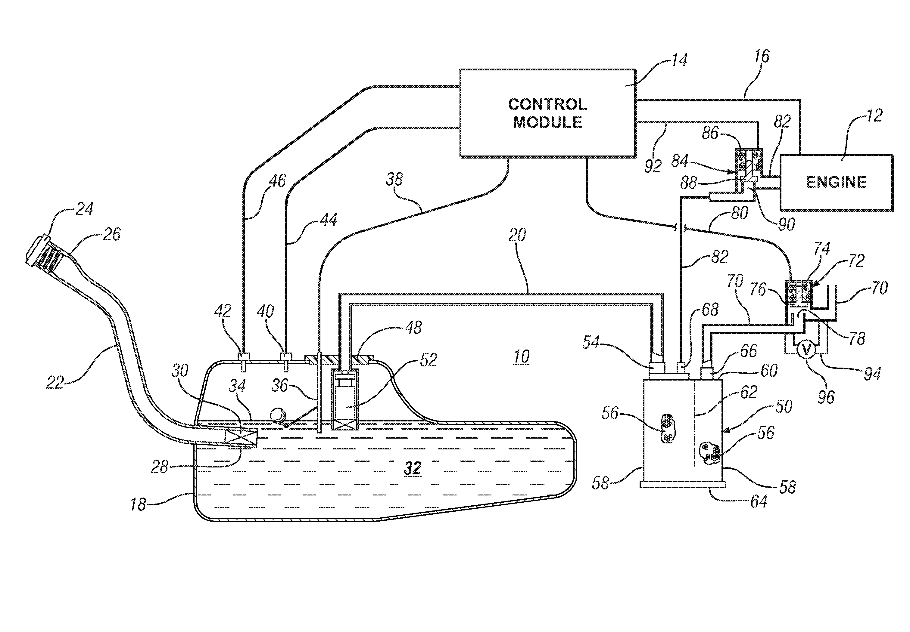
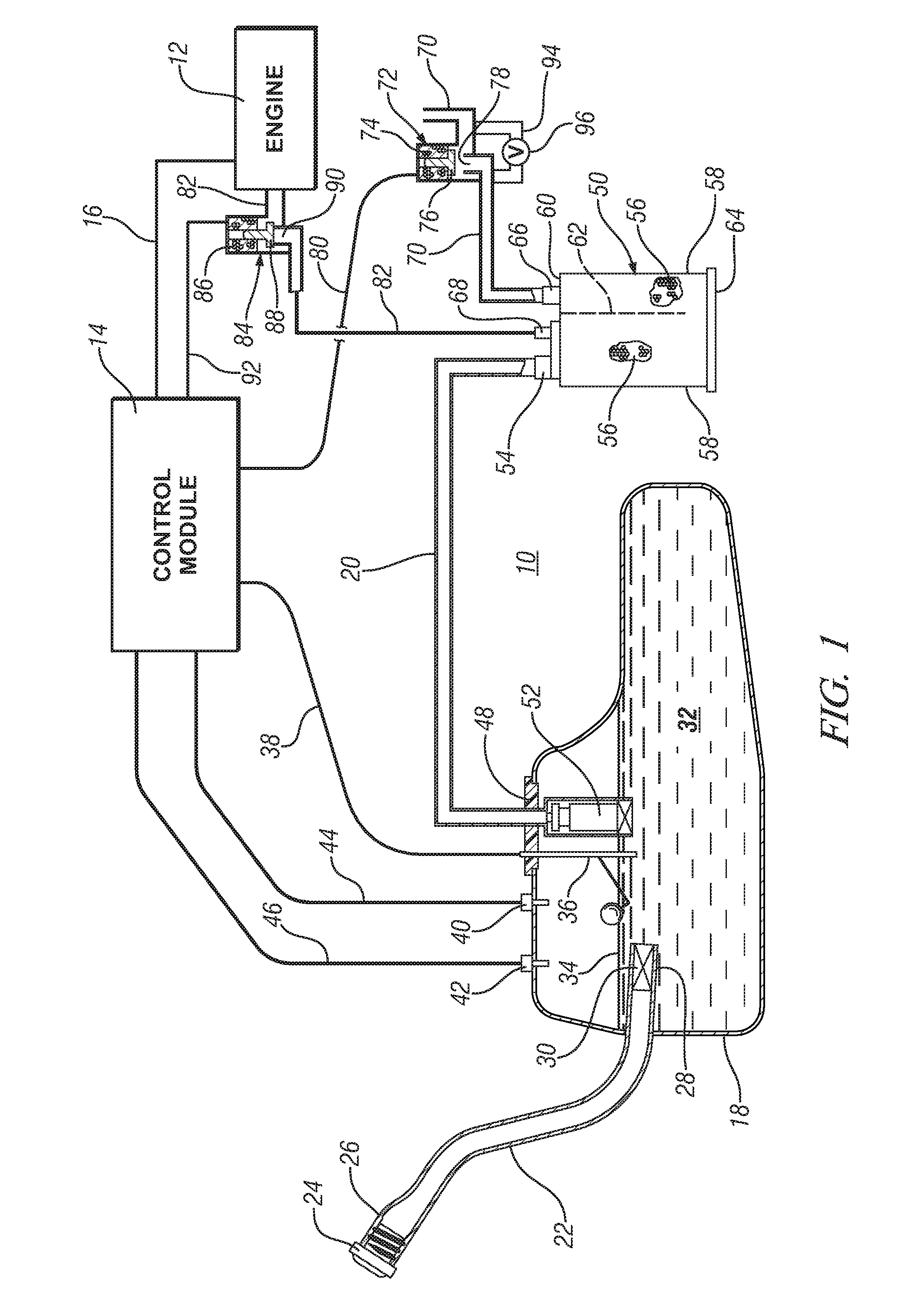
[0013]A plug-in hybrid automotive vehicle has a suitable re-chargeable battery system that typically powers at least one electric motor for driving at least two wheels of the vehicle. As the vehicle operator drives the vehicle, a programmed computer is used to manage the operation of the electric motor and motive power delivered to the wheels in response to operator demand. While the battery system may be charged when the vehicle is not being driven, vehicle range even with a fully charged battery system is limited. In the subject hybrid electric motor-powered vehicle, an on-board gasoline powered engine is provided to power an electric generator to drive the electric motor when the battery reaches a low-charge condition. The focus of this invention and the following illustrations is on the fuel tank and evaporative emission control system for the plug-in hybrid vehicle gasoline engine.

[0014]Fuel evaporative emission control systems have been in use on gasoline engine driven automot...


PUM


Abstract

A plug-in hybrid vehicle is driven by one or more electric motors powered by a battery system with supplemental electric power provided by a gasoline engine powered generator. A canister, connected by a fuel vapor vent passage, is used to admit and temporarily adsorb fuel vapor from a vehicle fuel tank during refueling. The canister also has a first fuel vapor and air flow passage for venting the canister and introducing ambient air (in the reverse flow direction) for removing vapor stored in the canister during tank refueling. The canister has a second passage for conducting air and purged vapor from the canister to the operating engine. The first and second passages are opened only during engine operation for purging of stored fuel vapor. The first flow passage is selectively opened when the tank is being refueled. The sealed fuel system eliminates diurnal fuel tank vapor generation and canister bleed emissions.

Description

TECHNICAL FIELD[0001]This invention pertains to the management of fuel tank gasoline vapor produced in operation of battery powered, electric motor driven automotive vehicles having a gasoline engine for generating supplemental electrical power on extended driving trips. The evaporative emission management process also enables periodic testing for fuel tank leaks and for assessment of the current Reid Vapor Pressure of on-board fuel.BACKGROUND OF THE INVENTION[0002]There is interest in producing passenger vehicles driven by an electric motor powered by a re-chargeable battery (for example, a lithium-ion battery). The operating range of the battery powered vehicle would be increased using an on-board electric generator driven, upon demand, by a gasoline engine. For relatively short driving excursions, the capacity of the battery would suffice and the gasoline engine would not be started. At the completion of such trips the battery would be recharged from a 110 volt AC source. Such a ...

Claims


Application Information

Patent Timeline
Patent Type & Authority Patents(United States)
IPC IPC(8): F02M33/02F02M33/04
CPCB60K15/03519F02D41/0032F02M25/08F02M25/0809B60K2015/03571B60K2015/03576F02M2025/0845B60K15/077
Inventor REDDY, SAM R.MC CARTHY, TIMOTHY E.
Owner GM GLOBAL TECH OPERATIONS LLC
Why Eureka
Try Eureka