Elevator installation

Active Publication Date: 2008-11-11
TK ELEVATOR INNOVATION & OPERATIONS GMBH
View PDF20 Cites 35 Cited by
  • Summary
  • Abstract
  • Description
  • Claims
  • Application Information

AI Technical Summary

Benefits of technology

[0011]While the critical distance is usually set such that it corresponds in any event to at least the sum of the braking distances which are covered when braking the car from its current speed to the speed of zero during an emergency stop and in addition also with the safety gear acting, it is provided according to the invention that the critical distance can be determined in accordance with a prescribable emergency stop triggering curve and the minimum distance can be determined in accordance with a prescribable safety gear triggering curve, the safety gear triggering curve not touching the emergency stop traveling curve and it being possible to trigger the safety gear already even before the at least one car has reached the location with which the speed of zero is associated according to the emergency stop traveling curve, that is when an emergency stop is properly performed. This makes it possible in particular that the safety gear can already be triggered while the car is still covering the distance during which it is braked when an emergency stop is properly performed. It is therefore no longer necessary to wait to see whether, after triggering the emergency stop, the car is properly braked by means of the brake associated with it before triggering the safety gear, if necessary, but instead the safety gear can be triggered irrespective of whether or not braking is properly performed during an emergency stop.
[0015]In order to ensure that the safety gear is not triggered when an emergency stop is properly performed, in which the movement of the car follows the emergency stop traveling curve, in a preferred embodiment the emergency stop traveling curve is offset at the speed of zero by a prescribable distance value in relation to the safety gear traveling curve. By offsetting the emergency stop traveling curve, the stopping point of the car after carrying out an emergency stop is spaced apart from the stopping point of the car after braking by means of the safety gear. The distance between the two stopping points corresponds to the prescribed distance value. These different stopping points make it possible to ensure in a structurally simple way that the safety gear is not mistakenly triggered when the emergency stop is properly performed.
[0018]It is of advantage if the critical distance and the minimum distance can be determined independently of each other. In an embodiment of this type, it is in particular not required for the minimum distance first to be determined for the determination of the critical distance.
[0019]It is advantageous if the car can be braked in normal operation by means of the control unit in accordance with a prescribable operational deceleration curve, the operational deceleration curve, the emergency stop traveling curve and the safety gear traveling curve being offset at the speed of zero both in relation to one another and in relation to the position of an obstacle, another car or an end of the shaft. The offset disposition of the curves in relation to one another ensures that an emergency stop is not triggered and the safety gear is not activated when the car is braked in the operationally proper manner by means of the control unit. If an emergency stop is triggered and emergency stop braking of the car takes place in the proper manner, the safety gear is not triggered on account of the offset disposition of the curves. The offset disposition of all the curves in relation to the position of an obstacle, another car or an end of the shaft ensures that the car is in any event brought to a standstill at a stopping point which is disposed at the safety distance from the obstacle, from another car or from an end of the shaft.
[0044]It is of particular advantage if, in addition to the position of the associated car, the position sensor also transmits to the safety device its speed and / or its direction of movement.

Problems solved by technology

The emergency stop triggering curve incorporates not only the actual braking behavior of the at least one car when an emergency stop is performed, but also possible delay times between the triggering of the emergency stop and the coming into effect of the brake.

Method used


Image

  • Elevator installation
  • Elevator installation
  • Elevator installation

Examples


Embodiment Construction

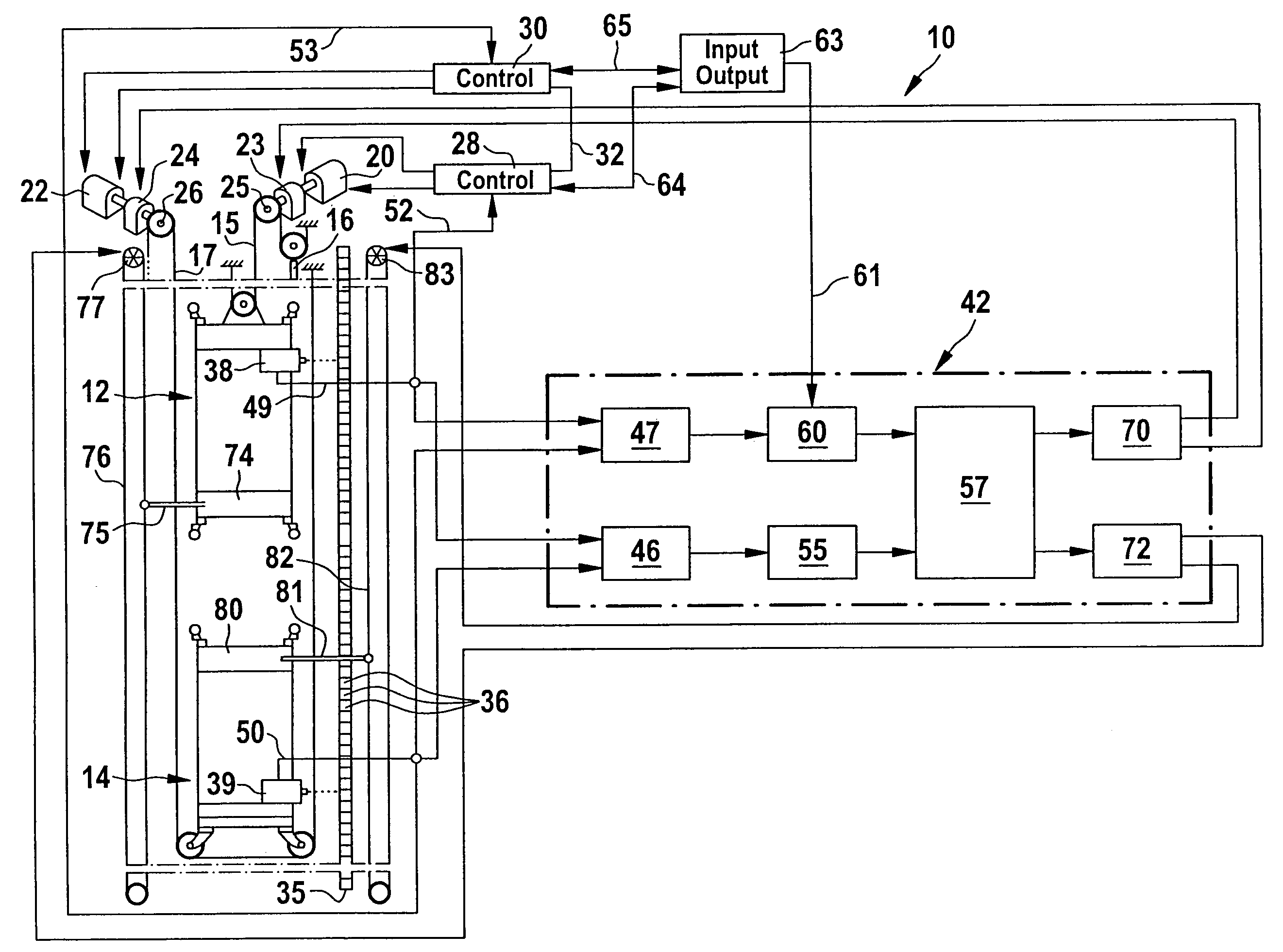
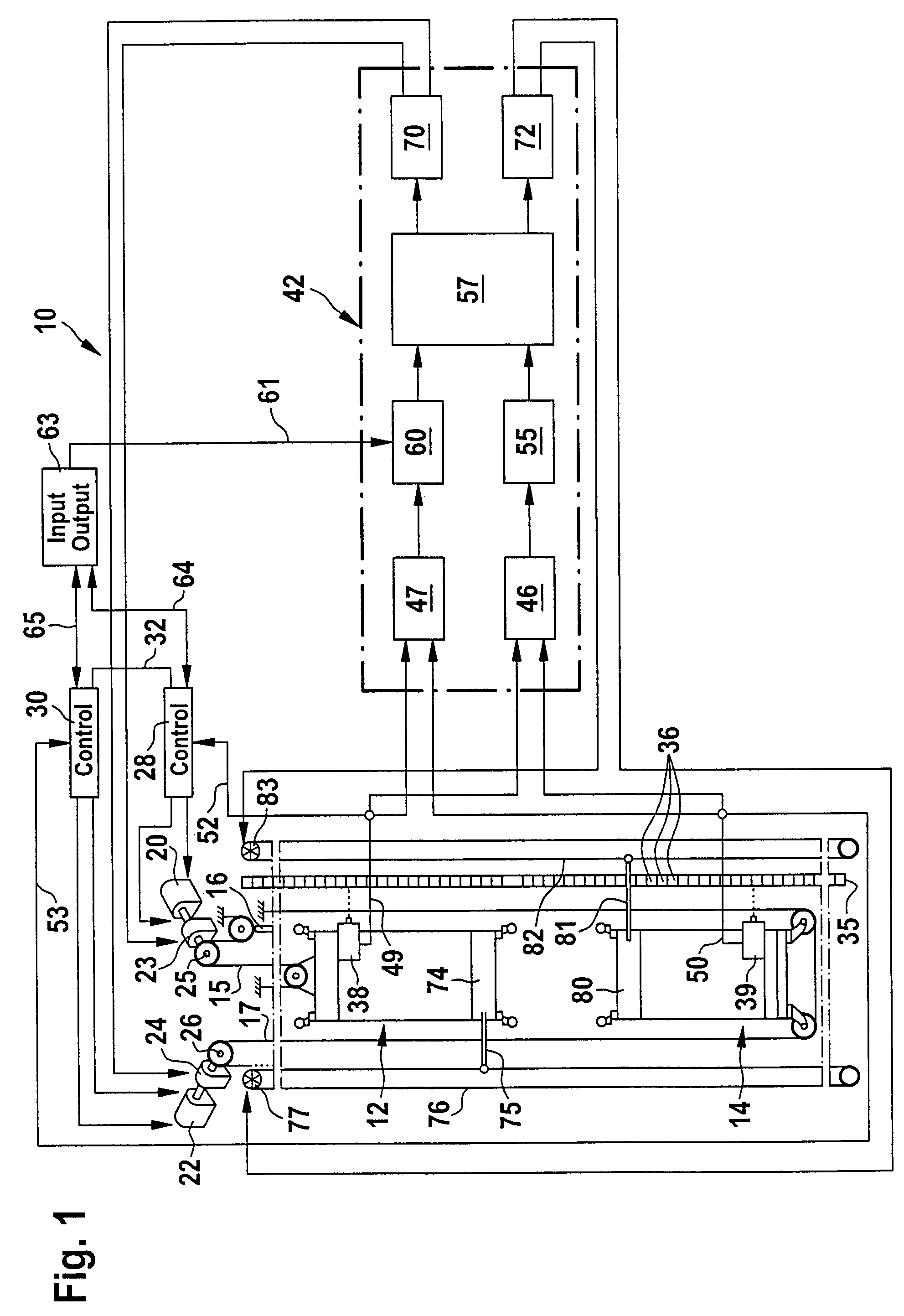
[0053]In FIG. 1, a preferred embodiment of an elevator installation according to the invention is represented in a greatly schematized form and provided overall with the reference numeral 10. It comprises two cars 12, 14, which are disposed one above the other in a shaft (not represented in the drawing) and can be made to travel up and down independently of each other along a common traveling path, which is known per se and therefore not represented in the drawing. The upper car 12 is coupled to a counterweight 16 via a suspension rope 15. The lower car 14 is held on a suspension rope 17, which interacts in a way corresponding to the suspension rope 15 with a counterweight, which however is not represented in the drawing in order to achieve a better overview.

[0054]A separate drive in the form of an electric drive motor 20 and 22 respectively is associated with each car 12, 14, and in each case also a separate electromechanical brake 23 and 24, respectively. A traction sheave 25 and ...


PUM


Abstract

The invention relates to an elevator installation comprising at least one car, which has a safety gear and with which a control unit, a drive and a brake are associated, and further comprising a safety device for avoiding a collision of the car with an obstacle, another car or an end of the shaft, it being possible by means of the safety device to compare an actual distance of the car from an obstacle, another car or an end of the shaft with a minimum distance and a critical distance. If the actual distance goes below the minimum distance, an emergency stop can be triggered. If the actual distance goes below the critical distance, the safety gear of the car can be triggered. In order to develop the elevator installation in such a way that the distance that is to be maintained at the least by the car from an obstacle, another car or an end of the shaft can be reduced without an emergency stop or a safety gear being triggered, but a car collision can be reliably prevented, it is proposed that it is possible by means of the determining unit of the safety device to determine the critical distance in accordance with a prescribable emergency stop triggering curve and the minimum distance in accordance with a prescribable safety gear triggering curve, the safety gear triggering curve not touching the emergency stop traveling curve, and that it is possible to trigger the safety gear even before the car has reached the location with which the speed of zero is associated according to the emergency stop traveling curve.

Description

[0001]This application is a continuation of international application number PCT / EP2005 / 011540 filed on Oct. 28, 2005.[0002]The present disclosure relates to the subject matter disclosed in international application number PCT / EP2005 / 011540 of Oct. 28, 2005 and European application number 05 004 882.6 of Mar. 5, 2005, which are incorporated herein by reference in their entirety and for all purposes.BACKGROUND OF THE INVENTION[0003]The invention relates to an elevator installation comprising at least one car, which can be made to travel in a shaft along a traveling path and has a safety gear, wherein a control unit, a drive and a brake are associated with the car, and further comprising a safety device with a speed determining unit for determining the current speed of the at least one car, a distance determining unit for determining the actual distance of the at least one car from an obstacle, another car or an end of the shaft, and a determining unit for determining a critical dista...

Claims


Application Information

Patent Timeline
Patent Type & Authority Patents(United States)
IPC IPC(8): B66B5/06
CPCB66B5/0031B66B1/28B66B5/00
Inventor NUEBLING, WALTER
Owner TK ELEVATOR INNOVATION & OPERATIONS GMBH
Why Eureka
Try Eureka