Spacer profile for an insulated glazing unit

a spacer profile and glazing technology, applied in the direction of building components, tubular articles, hollow wall articles, etc., can solve the problems of direct access of water vapor present in the production environment to the particulate adsorbent material, hindered, etc., and achieve the effect of increasing the compressive strength of the profile and maximizing the ability to absorb water vapor

Inactive Publication Date: 2008-11-11
ENSINGER KUNSTTECH
View PDF70 Cites 20 Cited by
  • Summary
  • Abstract
  • Description
  • Claims
  • Application Information

AI Technical Summary

Benefits of technology

[0010]Due to the fact that the particulate adsorbent material is embedded in a binder matrix which is permeable to water vapor, the direct access of water vapor present in the production environment to the particulate adsorbent material is, on the one hand, hindered, since the adsorption rate is governed by the water-vapor permeability, ie the rate at which water vapor passes through the binder matrix to reach the particles of adsorbent material, and is thus considerably slower and consequently less than when water vapor has free access to the particulate adsorbent materials, as is conventionally the case.
[0058]Surprisingly, it has been found that when use is made of organic binding agents, the tempering step required for the expulsion of the processing agent, which can take place, for example, at 200° C., increases the compressive strength of the profile to a marked degree on account of crosslinking mechanisms in the matrix.

Problems solved by technology

Due to the fact that the particulate adsorbent material is embedded in a binder matrix which is permeable to water vapor, the direct access of water vapor present in the production environment to the particulate adsorbent material is, on the one hand, hindered, since the adsorption rate is governed by the water-vapor permeability, ie the rate at which water vapor passes through the binder matrix to reach the particles of adsorbent material, and is thus considerably slower and consequently less than when water vapor has free access to the particulate adsorbent materials, as is conventionally the case.

Method used


Image

  • Spacer profile for an insulated glazing unit
  • Spacer profile for an insulated glazing unit
  • Spacer profile for an insulated glazing unit

Examples


Embodiment Construction

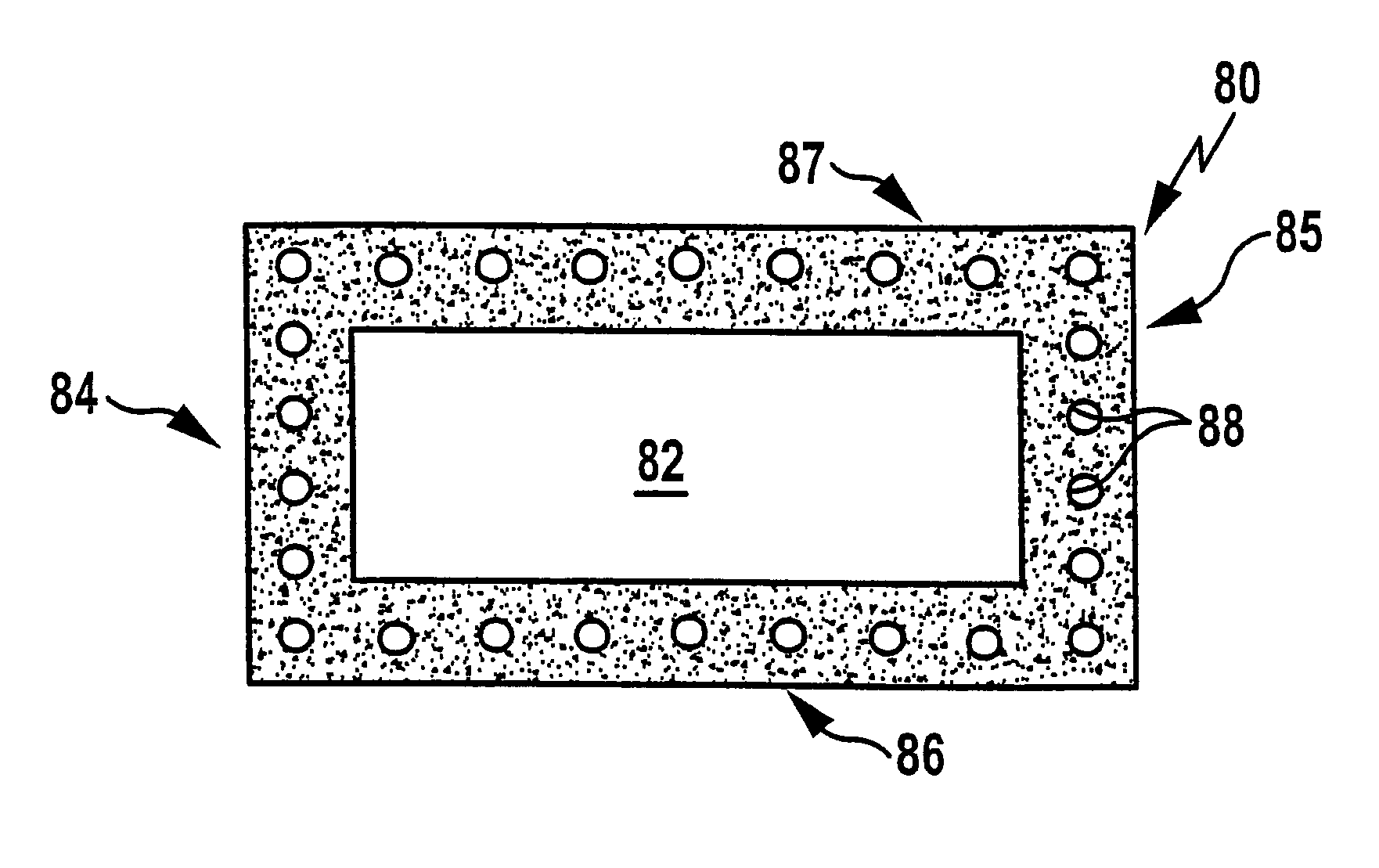
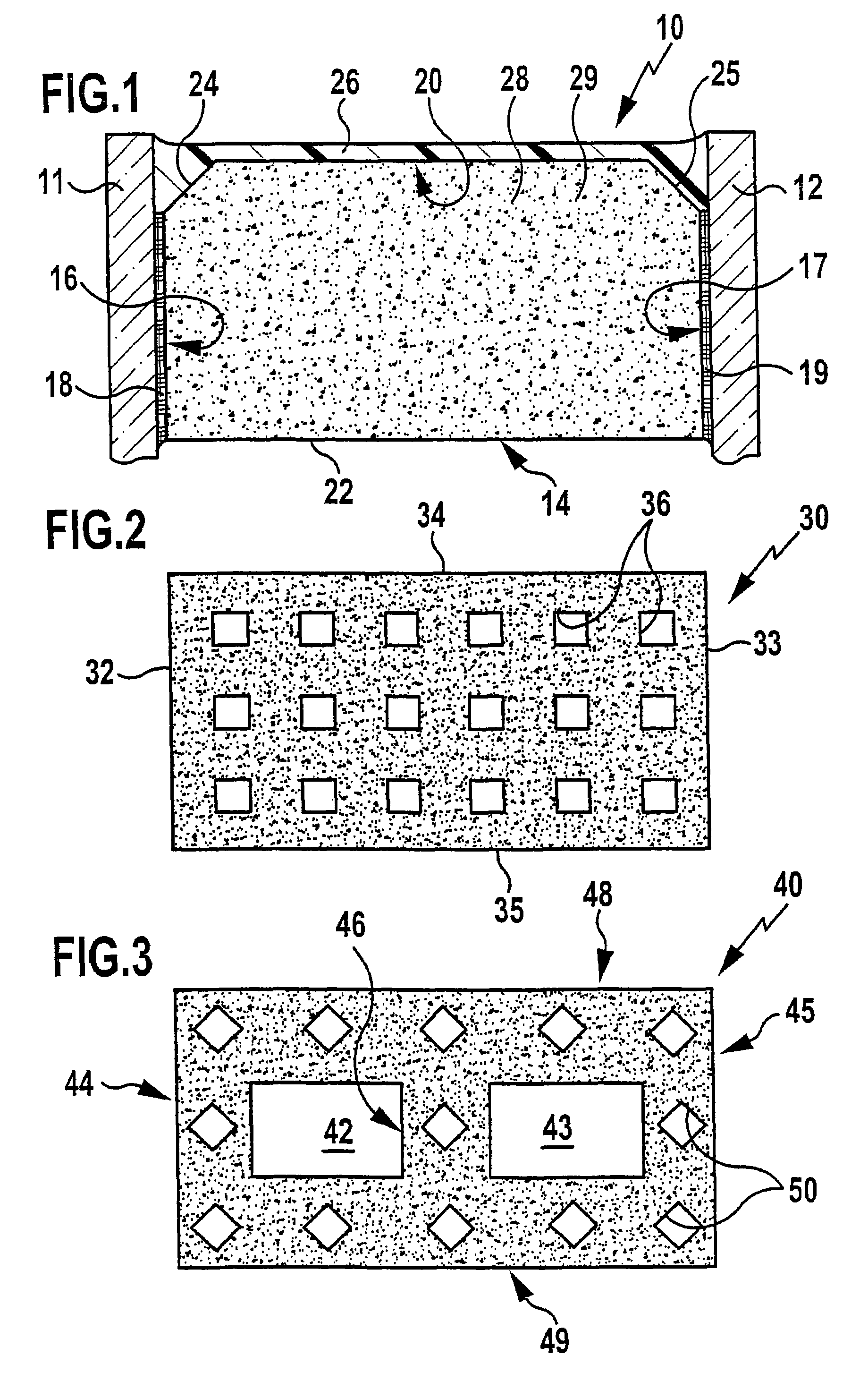
[0062]FIG. 1 shows part of a sectional view of an insulated glazing unit designated, as a whole, by the reference numeral 10 and comprising two panes of glass 11, 12 which are held in parallel relationship at a specified distance from each other by means of a spacer profile 14. The cross-section of the spacer profile 14 is substantially based on a rectangle and the side walls 16, 17 of the spacer bear against the panes of glass 11, 12. Connection of the side walls 16, 17 to the respective pane of glass 11 or 12 is achieved by an adhesive layer 18, 19.

[0063]Between the side walls 16, 17 there extends a first transverse wall 20 and a second transverse wall 22, and these and the side walls 16, 17 substantially define the cross-section of the profile.

[0064]When the spacer profile 14 is installed in the insulated glazing unit, the transverse wall 20 is positioned at the outer edge of the insulated glazing unit 10 and is angular at its ends so as to give chamfered areas 24, 25. Once the s...


PUM

PropertyMeasurementUnit
pore sizesaaaaaaaaaa
particle sizeaaaaaaaaaa

Abstract

In order to provide a spacer profile for an insulated glazing unit, which profile has a cross-section based on a rectangular shape, is provided with two parallel spaced side walls which, when said insulated glazing unit is assembled, will be placed against the panes of glass to be kept apart from each other, and is further provided with first and second transverse walls which extend between said side walls and of which the first will be adjacent to the edge of the glazing unit and the second will face the space between the panes, with the intention of enabling simple handling of said profile when assembling the spacer frame whilst maintaining a high absorptive capacity for water vapor, it is proposed that said spacer profile comprises a binder matrix and, embedded therein, a particulate adsorbent material for water vapor, and that the binder matrix is permeable to water vapor.

Description

[0001]This application is a continuation of PCT application No. PCT / EP2004 / 002649 filed Mar. 13, 2004 and claims priority to German application No. 103 11 830.6 of Mar. 14, 2003, both of which are incorporated herein by reference in their entirety and for all purposes.BACKGROUND OF THE INVENTION[0002]The present invention relates to a spacer profile for an insulated glazing unit, which profile has a cross-section based on a rectangular shape, is provided with two parallel spaced side walls which, when said insulated glazing unit is assembled, will be placed against the panes of glass to be kept apart from each other, and is further provided with first and second transverse walls which extend between said side walls and of which the first will be adjacent to the edge of the glazing unit and the second will face the space between the panes. By the use of sealants, the space formed between the panes of glass is sealed from the edge of each pane, and the use of a desiccant ensures that ...

Claims


Application Information

Patent Timeline
Patent Type & Authority Patents(United States)
IPC IPC(8): B29D22/00B29D24/00B32B3/20E06B7/12E06B3/663E06B3/677
CPCB01D53/261E06B3/66328E06B3/677B01J20/18B01J20/2803B01J20/2808B01J20/28004B01J20/103B01J20/28047B01D53/28Y10T428/139B01D2253/106B01D2253/108B01D2253/116B01D2253/304B01D2253/308B01D2259/4508B01D2259/4591B01J2220/46Y10T428/24744Y10T428/24562B82Y40/00E06B3/663E06B3/667E06B3/67
Inventor ENSINGER, WILFRIED
Owner ENSINGER KUNSTTECH
Why Eureka
Try Eureka