Exposure control method of imaging apparatus

a technology of exposure control and imaging apparatus, which is applied in the direction of exposure control, optical radiation measurement, camera filters, etc., can solve the problems of deterioration in resolution performance and resolution performance, and achieve the effect of adequate image quality and image quality

Inactive Publication Date: 2008-11-11
SONY CORP
View PDF7 Cites 15 Cited by
  • Summary
  • Abstract
  • Description
  • Claims
  • Application Information

AI Technical Summary

Benefits of technology

[0011]The present invention is proposed in view of the above-mentioned circumstances. Therefore, an object of the present invention is to protect an image quality deterioration by an exposure control and reserve a sufficient image quality with respect to an imaging apparatus having means for carrying out an exposure adjustment by placing and removing an ND filter in and from an iris opening, and at least one exposure adjusting means for the other exposure adjustment.

Problems solved by technology

For this reason, there is inevitably a difference with regard to imaging points between the beam transmitted through the ND filter and the beam transmitted through the air that is not covered by the ND filter, and thereby, this consequently causes deterioration in the resolution performance.
Simultaneously, when the ND filter becomes at the half covered state, since there is an edge of the ND filter in an optical path, the diffraction phenomenon at the edge causes the deterioration in the resolution performance.

Method used


Image

  • Exposure control method of imaging apparatus
  • Exposure control method of imaging apparatus
  • Exposure control method of imaging apparatus

Examples


Embodiment Construction

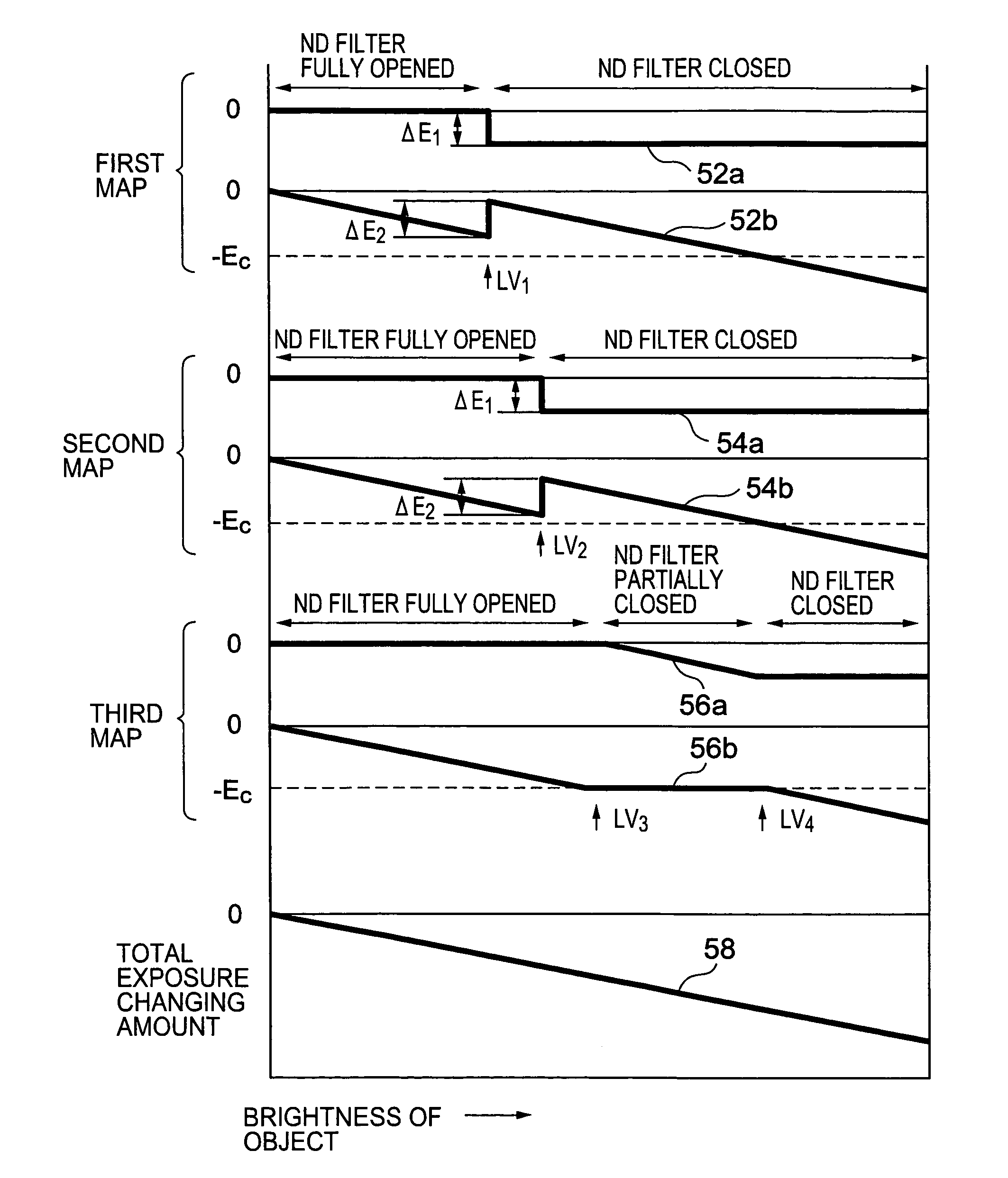
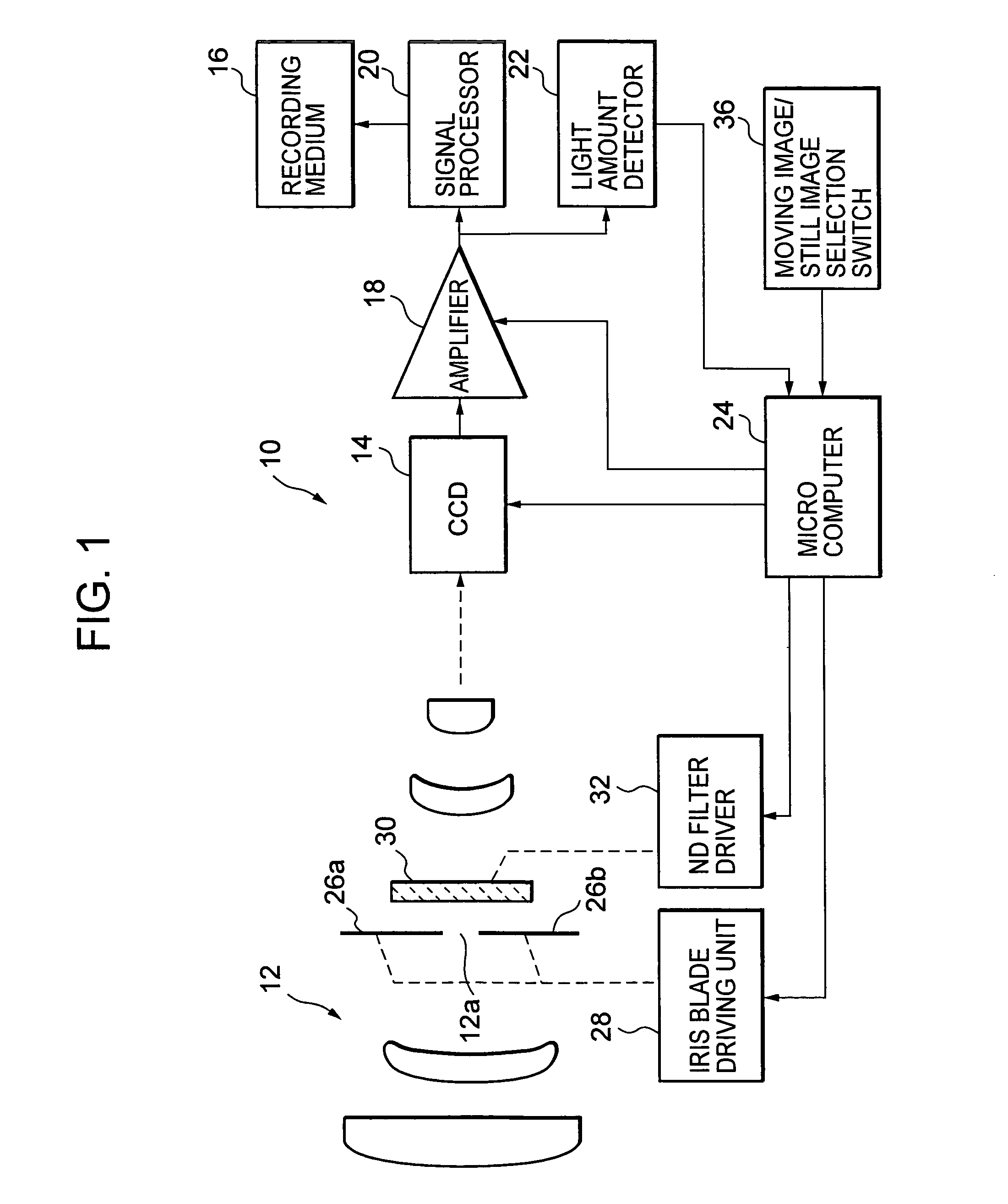
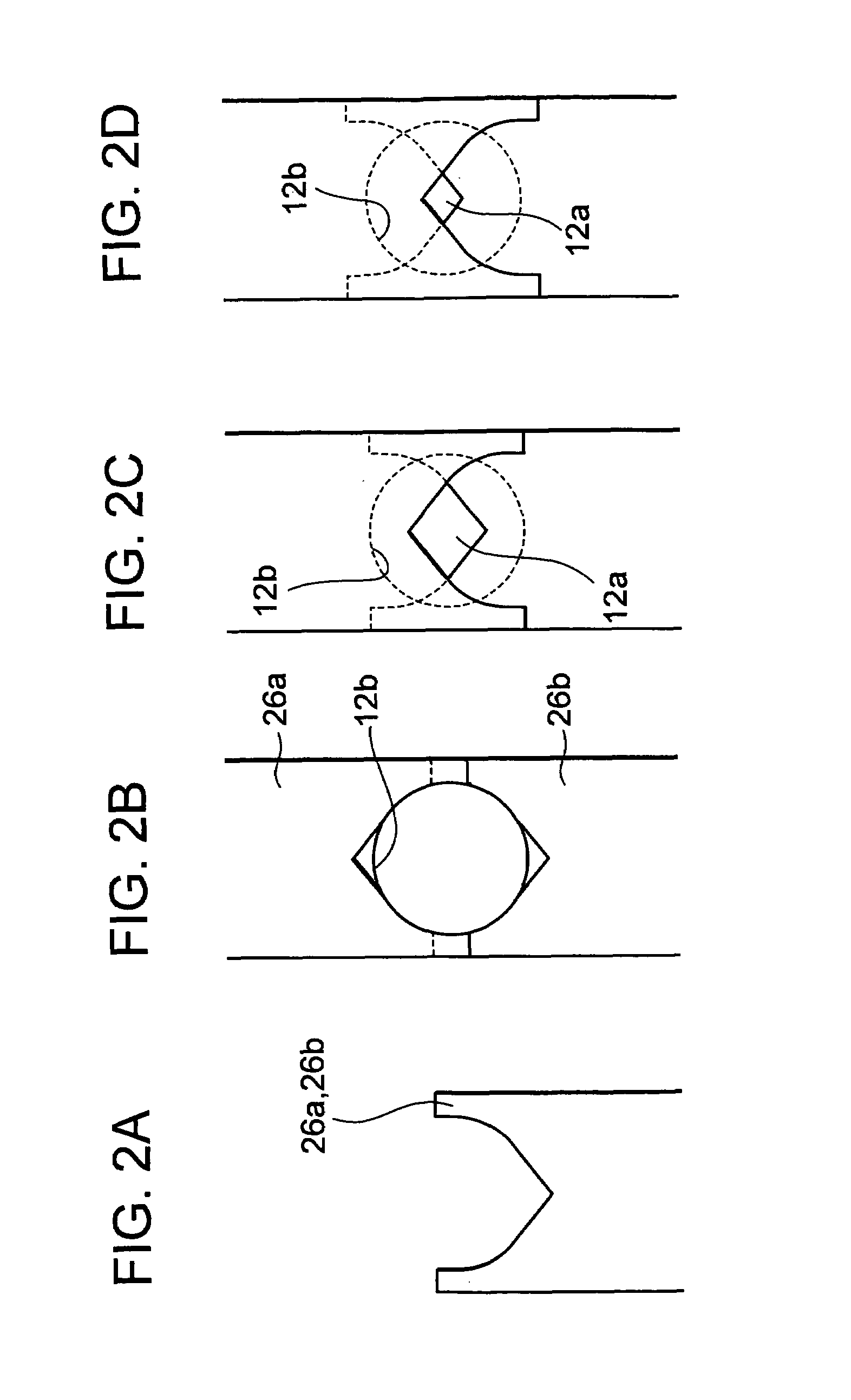
[0026]An embodiment of the present invention will be described below. FIG. 1 is a block diagram showing specific configuration example of an imaging apparatus that is able to execute an exposure control method according to an embodiment of the present invention, FIGS. 2A to 2D are views showing shapes and operation of iris blades of the imaging apparatus in FIG. 1, and FIG. 3 is a view showing a data content of a map data stored in the imaging apparatus of FIG. 1 with a shape of a graph.

[0027]An imaging apparatus 10 shown in FIG. 1 includes an image taking lens 12, a CCD 14 that is a solid state imaging device, and a recording medium 16 for image data. The imaging apparatus 10 has a moving image taking mode and a still image taking mode, and they are able to be selected by a user. Thus, this imaging apparatus 10 serves as the imaging apparatus that is able to be used as a video camera for taking a moving image and also is able to be used as a digital still camera for taking a still ...


PUM


Abstract

When a brightness level of an object is below a predetermined level, an ND filter is removed from an iris opening to fully open the iris opening, and when the brightness level of the object is above a predetermined level, the ND filter is placed to the iris opening to fully close the iris opening. When the ND filter is moved between the fully-opened state and the fully-closed state, an exposure change amount corresponding to an amount offsetting the exposure change amount due to a state transition is generated by controlling iris blades.

Description

CROSS REFERENCE TO RELATED APPLICATION[0001]This application claims priority from Japanese Priority Document No. 2003-278978, filed on Jul. 24, 2003 with the Japanese Patent Office, which document is hereby incorporated by reference.BACKGROUND OF THE INVENTION[0002]1. Field of the Invention[0003]The present invention relates to an exposure control method of an imaging apparatus such as a video camera, a digital still camera and the like which uses a solid state imaging device, for example.[0004]2. Description of the Related Art[0005]An imaging apparatus such as a video camera, a digital still camera and the like which uses a solid state imaging device, includes means for adjusting an opening area of an iris opening of an image taking lens as an exposure adjusting means, means for adjusting an electronic shutter speed of the solid state imaging device, means for adjusting an amplifier gain of an image signal obtained from the solid state imaging device, and the like.[0006]In all of t...

Claims


Application Information

Patent Timeline
Patent Type & Authority Patents(United States)
IPC IPC(8): H04N5/238H04N5/225G03B7/28G03B7/097G03B9/02G03B11/00H04N5/235H04N5/243
CPCH04N5/238H04N23/75G03B9/02G03B7/097
Inventor TERAI, TAKASHINANJO, YUSUKETAKAHASHI, KUNIOKIOKAJIMA, KOJIMATSUMOTO, ASUKA
Owner SONY CORP
Why Eureka
Try Eureka