Lens unit and imaging apparatus

a technology of lens unit and imaging apparatus, which is applied in the direction of generator/motor, camera, instruments, etc., can solve the problems of preventing further reduction of size, affecting the quality of captured images, so as to reduce size, simplify the mechanism of lens unit, and eliminate the space for such guiding means

Active Publication Date: 2008-11-11
SONY CORP
View PDF20 Cites 20 Cited by
  • Summary
  • Abstract
  • Description
  • Claims
  • Application Information

AI Technical Summary

Benefits of technology

[0008]Furthermore, there is provided a clearance of several microns for enabling the movement of the movable section smoothly on the guide shafts between the guide shaft and a bearing section. However, the clearance may also allow minute lateral movement of the movable section and / or inclination of the movable section with respect to the optical axis. Such a lateral movement and inclination of the movable section may cause a deterioration in quality of a captured image because an image focal point may deviate or a so-called image-shake phenomenon where an image in the image focal plane may slightly shake. Particularly, in portable devices, the movement of the movable section within the plane orthogonal to the optical axis direction and the inclination to the optical axis may occur easily due to changes in its orientation or vibrations generated by various disturbances, such as shock and shake applied to the devices, etc.
[0018]Accordingly, the movable section may be moved in the optical axis direction without causing the movable section to incline or deviate with respect to the optical axis.
[0019]Furthermore, in the embodiments of the present invention, any guiding means, such as a guide shaft, for guiding the movable section in the optical axis direction is not required. Accordingly, it is possible to achieve a reduction in size by simplifying the mechanism of the lens unit and eliminating the space for such guiding means.

Problems solved by technology

However, the above-mentioned imaging apparatus has the guide shaft for guiding the movable section, which has a technical issue that it requires a space for accommodating the guide shaft, thus preventing it from achieving a further reduction of size.
Such a lateral movement and inclination of the movable section may cause a deterioration in quality of a captured image because an image focal point may deviate or a so-called image-shake phenomenon where an image in the image focal plane may slightly shake.
Particularly, in portable devices, the movement of the movable section within the plane orthogonal to the optical axis direction and the inclination to the optical axis may occur easily due to changes in its orientation or vibrations generated by various disturbances, such as shock and shake applied to the devices, etc.

Method used


Image

  • Lens unit and imaging apparatus
  • Lens unit and imaging apparatus
  • Lens unit and imaging apparatus

Examples


Embodiment Construction

[0046]Below, embodiments of the present invention will be described with reference to the accompanying drawings. The present invention is applicable to various types of imaging apparatuses, such as a mobile phone, a video camera, a still camera, etc., which have a function of capturing a video or a still image, or to various types of lens units used for these imaging apparatuses.

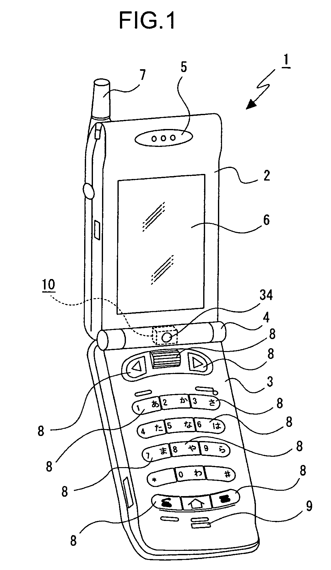
[0047]As an example of an imaging apparatus 1, there is provided a mobile phone, as shown in FIG. 1. The imaging apparatus 1 is such that a first casing 2 and a second casing 3 are combined to form a foldable structure in conjunction with a hinge section 4.

[0048]The first casing 2 is provided with a speaker 5, a display section 6, and an antenna 7. This antenna 7 is configured to be extendable.

[0049]The second casing 3 is provided with various types of operating units 8, including a push button, a rotary dial, a microphone 9 and the like.

[0050]An imaging unit 10 is built into the hinge section 4. One of the ...


PUM


Abstract

A lens unit includes: a lens barrel; a movable section including a movable lens and configured to be moved in an optical axis direction relative to the lens barrel; a linear actuator configured to move the movable section in the optical axis direction; and a biasing blade spring including a holding portion for holding the movable section, a plurality of spring portions capable of being elastically deformed and biasing the movable section in the optical axis direction, and an attachment portion to be attached to the lens barrel. The plurality of spring portions of the biasing blade spring are configured to restraint a movement force produced at the movable section in a plane orthogonal to the optical axis.

Description

BACKGROUND OF THE INVENTION[0001]1. Field of the Invention[0002]The present invention relates to a lens unit and an imaging apparatus. More specifically, the present invention relates to a lens unit having a movable section and an imaging apparatus including such a lens unit, which allows a reduction of size and an improvement in operation reliability of the movable section.[0003]2. Description of the Related Art[0004]A lens unit, which is constructed by disposing an imaging optical system such as a movable lens in a lens barrel, is included in various types of imaging apparatuses, such as a video camera and a still camera, as well as a mobile phone, etc. An example of such an imaging apparatus is one that is equipped with a movable section having a movable lens for zooming or focusing, in which the movable section can be moved by a linear actuator in the optical axis direction (for example, see Japanese Patent 3387173 and Japanese Patent Application Publication H08-015593).[0005]In...

Claims


Application Information

Patent Timeline
Patent Type & Authority Patents(United States)
IPC IPC(8): G03B17/00
CPCG02B7/026G03B30/00G02B7/105G02B13/009H02N2/02
Inventor MAKII, TATSUOUNEME, TAKATOSHI
Owner SONY CORP
Why Eureka
Try Eureka