Floor system

a floor system and floor technology, applied in the field of floor systems and methods, can solve the problems of metal floor systems, disadvantages of existing metal construction systems, and especially floor systems, and achieve the effects of improving the stability of the floor system

Active Publication Date: 2008-11-18
CEMCO LLC
View PDF47 Cites 30 Cited by
  • Summary
  • Abstract
  • Description
  • Claims
  • Application Information

AI Technical Summary

Problems solved by technology

Despite these advantages, however, existing metal construction systems, and especially floor systems, also suffer from disadvantages.
For example, one disadvantage present in existing metal floor systems involves a connection between the joists and the joist rims.
Although this system provides adequate structural properties, the measuring and connection of the separate clip angles to the joist rim is a time consuming process, which increases the labor costs in assembling the floor system.
However, this type of floor system also suffers from several disadvantages.
The monolithic tab structure also limits the practical dimensions of the joist connector tab because the strength requirements of the joist rim limit the dimensions of the resulting hole in the joist rim web.
In addition, the holes in the web of the joist rim remain open, which may result in a reduced ability of the joist rim to abate fire or noise passing through the joist rim.
Accordingly, it may be difficult or impossible to optimize the characteristics of both the joist rim and the joist connector tab.

Method used


Image

  • Floor system
  • Floor system
  • Floor system

Examples


Embodiment Construction

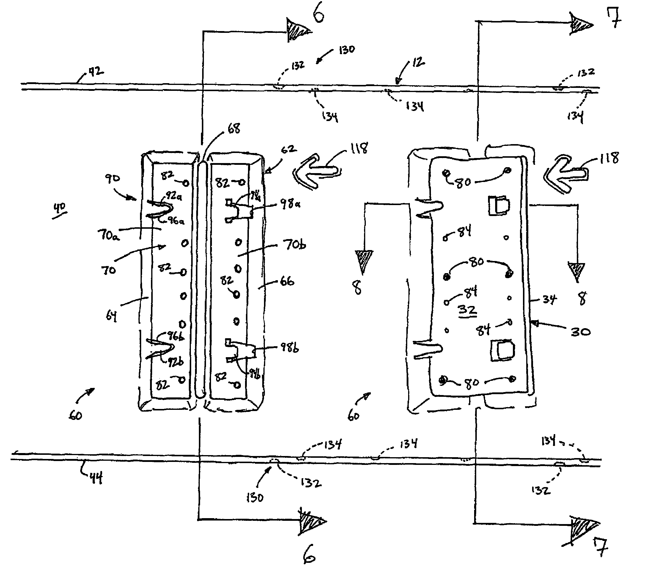
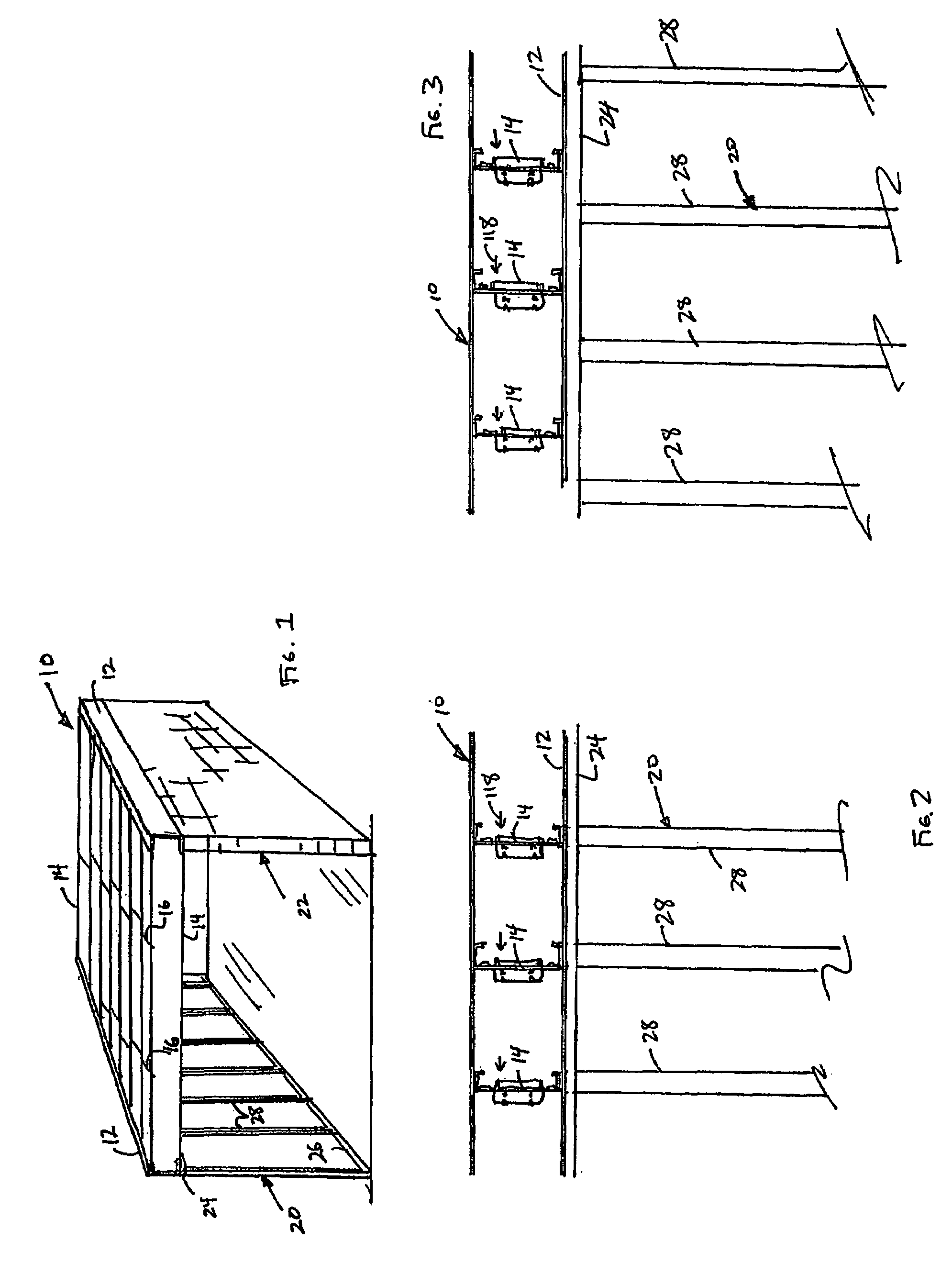
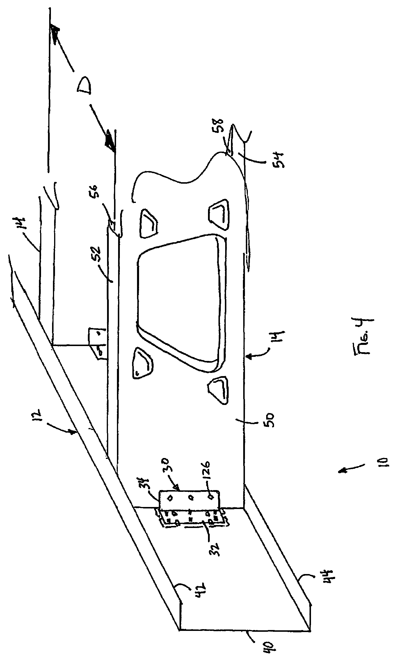
[0030]FIGS. 1-12 illustrate a preferred embodiment of a floor system, generally referred to by the reference numeral 10. The illustrated floor system 10 includes a pair of joist rims 12, or rim tracks and a plurality of joists 14 extending between the joist rims 12. Desirably, the joists 14 are coupled to the joist rims 12 to inhibit relative movement therebetween. If desired, one or more blocking members 16 may extend between, and be connected to, one or more adjacent pairs of joists 14. The blocking members 16 provide support to the joists 14 to inhibit the joists 14 from moving out of their vertical plane in response to a load being applied to the joists 14.

[0031]In the illustrated arrangement of FIG. 1, the floor system 10 is supported by a first wall 20 and a second wall 22. Desirably, the floor system 10 is supported at a first end by the first wall 20 and at a second end, opposite from the first end, by the second wall 22. Preferably, a first joist rim 12 of the floor system ...


PUM


Abstract

A floor system includes a pair of joist rim assemblies each having a web defining a first surface. The web also includes a mounting portion defining a second surface offset from the first surface. The joist rim may also include a prong defining a slot along with the web. A joist connector bracket is received within the slot and is connectable to the mounting portion of the web. A joist extends between the pair of joist rim assemblies and is connected to the joist connector bracket of each joist rim assembly.

Description

BACKGROUND OF THE INVENTION[0001]1. Field of the Invention[0002]The present invention relates to building construction systems and methods in general and, more specifically, to a floor system and method.[0003]2. Description of the Related Art[0004]Metal building products have become increasingly popular for use in new building construction as an alternative to wood-based building products. For example, metal building products are presently utilized in wall systems and floor systems of residential and commercial buildings. Metal wall systems and floor systems provide many advantages over wood-based products, including a higher strength-to-weight ratio, more consistent quality, and increased useful life.[0005]Despite these advantages, however, existing metal construction systems, and especially floor systems, also suffer from disadvantages. For example, one disadvantage present in existing metal floor systems involves a connection between the joists and the joist rims. In a typical fl...

Claims


Application Information

Patent Timeline
Patent Type & Authority Patents(United States)
IPC IPC(8): E04B1/00
CPCE04B5/10Y10T403/4605Y10T403/4642Y10T403/7176Y10T403/4691Y10T403/606F16B2200/403F16B2200/503F16B9/058F16B9/052
Inventor HALL, GEORGINGUYEN, HOANGKAMPHAUSEN, HERB
Owner CEMCO LLC
Why Eureka
Try Eureka