Concrete cutter

a concrete cutter and cutting technology, applied in the field of sawing equipment and to sawing equipment, can solve the problems of increasing the risk of boom sections being lost or misplaced, long trailers being required to accommodate, and mixing of boom sections, so as to reduce stress, facilitate and reliably position, the effect of extending the cutting width of the concrete cutter

Active Publication Date: 2008-11-18
SPIDER CUT IP
View PDF8 Cites 7 Cited by
  • Summary
  • Abstract
  • Description
  • Claims
  • Application Information

AI Technical Summary

Benefits of technology

[0014]The improved concrete cutter of the present invention has obtained these objects. It provides for a concrete cutter having a longitudinally-extending primary boom that allows one or more saw carriage sub-assemblies to move along the length of the boom, each carriage being effectively “captured” by a plate assembly that is attachable to the underside of the boom. The plate assembly is continued with “wing-like” boom extensions that are hingedly integrated and secured at each end of the primary boom. In this way, the boom extensions can be easily and reliably positioned at each end of the primary boom when such is desired or required by the operator to extend the cutting width of the concrete cutter and without requiring that the boom extensions be removed from the concrete cutter. This configuration also allows the saw carriage sub-assemblies to be moved along the boom extensions and the boom extensions then moved upwardly and out of the way from the primary boom during transport of the concrete cutter. This configuration is also a benefit when maintenance of the carriage sub-assemblies is require, the placement of the carriage sub-assemblies along the boom extensions allowing the carriage sub-assemblies being raised to a position where work on them is more convenient to the user, including occasions when the blades must be replaced, for example.
[0015]The improved concrete cutter of the present invention has a boom and saw carriage sub-assembly where saw carriage alignment and spacing is variably-adjustable along the boom. This is accomplished by providing a drive means with the boom along which each saw carriage can be independently placed such that each saw carriage can move toward or away from the other saw carriage as is desired or required by the operator. Each saw carriage sub-assembly is height-variable such that each is self-adjusting to contours in the profile of the concrete slab that is being cut, independently of the other carriage sub-assembly. This self-adjusting feature also relieves stress along the boom which prevents the boom from potential deformation or cracking.

Problems solved by technology

In order to control this type of cracking, which cracking otherwise tends to be random and unsightly and also tends to weaken the pavement, grooves are cut in the surface of the pavement.
The obvious disadvantage of this arrangement is that the operator had to determine the correct head spacing and then manually attach or adjust a spacer bar for each specific sawing application.
If it was a large job that required weeks of sawing, often times the booms would be left behind when moving the span saw itself to the next job site or they would be damaged while in storage.
Furthermore, the boom sections tended to be matched to fit to one side or the other of the span saw, which could result in the boom sections being mixed up when they were being re-attached or re-installed for another job.
Sometimes, the boom sections would be stored for a season or two, depending upon what type of slab width the contractor is required to cut, further increasing the risk that boom sections could be lost or misplaced.
Another disadvantage of the span saws of the prior art is that, in order to transport a span saw with its booms attached, a very long trailer would be required to accommodate the full width of the saw.
Even with the booms attached in this fashion, they would also be vulnerable to damage since they tend to hang out very far from the main frame of the span saw.
Another disadvantage of the span saws of the prior art is that ground clearance was typically a problem, particularly when saws were transported from slab to slab.
It is also difficult to load these units onto trailers without an extra long ramp.
The bottom line is that the span saws of the prior art, in the view of these inventors, create major problems that are related to both a lack of mobility and an inability to provide for quick set-up.
That is, as the concrete saw blade is used, it also wears down, thereby distributing fine elemental contaminants at the point of cutting.
There is also no flexibility with the relative position of the saws and the concrete surface.
For example, there is little if any flexibility for the configuration of the prior art to adjust for “crowns” in the concrete that is being cut.
Rather than adjusting for such crowns, one carriage and blade will tend to simply cut more deeply than the other, resulting in excessive or uneven wear of the concrete-cutting blades that are used.
As discussed earlier, this leads to problems in proper attachment of the additional boom sections to the primary boom, misalignment of the added boom section and possible malfunctioning of the saws, and a risk of the loss or misplacement of the additional boom sections as the machine is moved between work sites and during storage in the off-season.

Method used


Image

  • Concrete cutter
  • Concrete cutter
  • Concrete cutter

Examples


Embodiment Construction

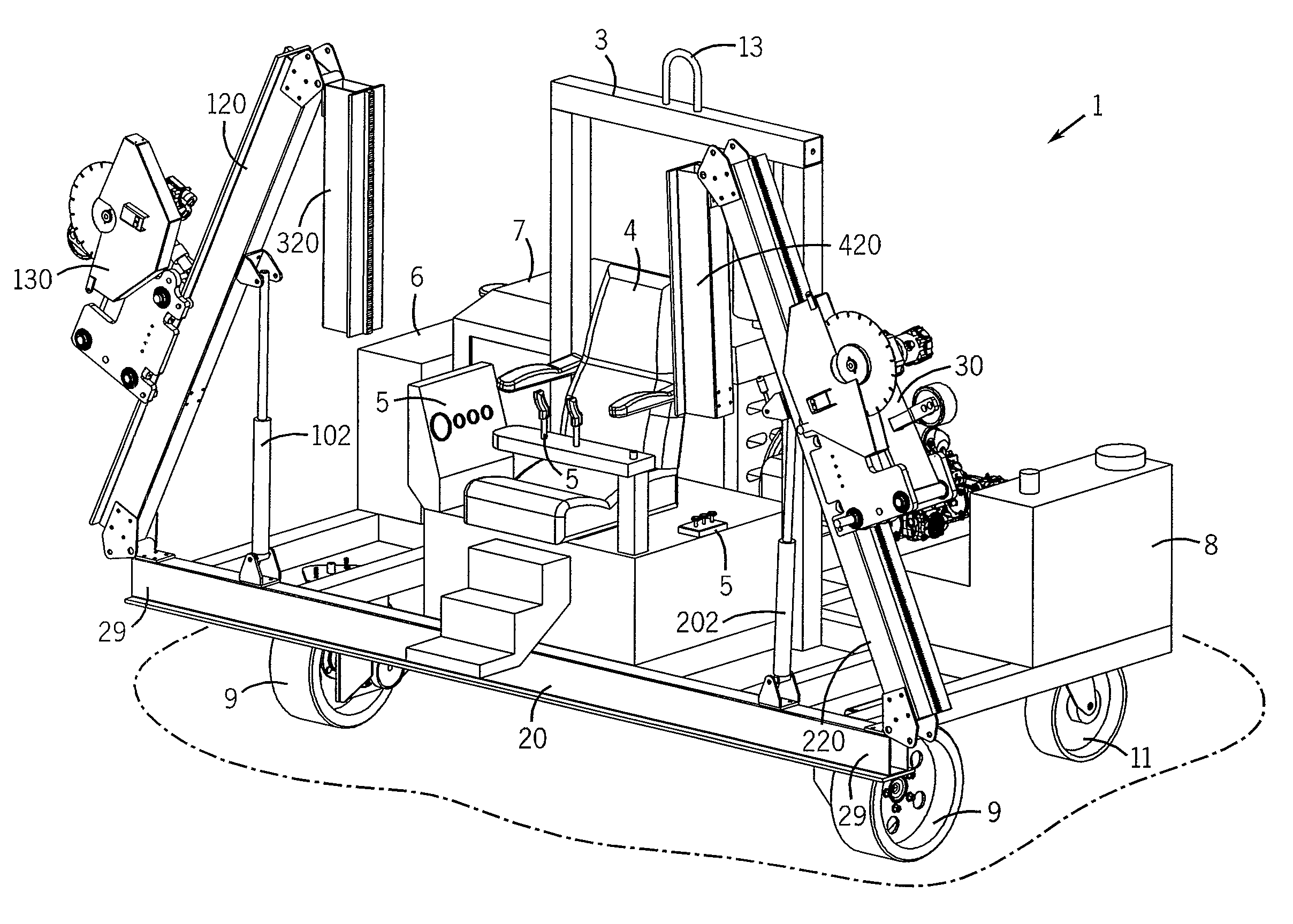
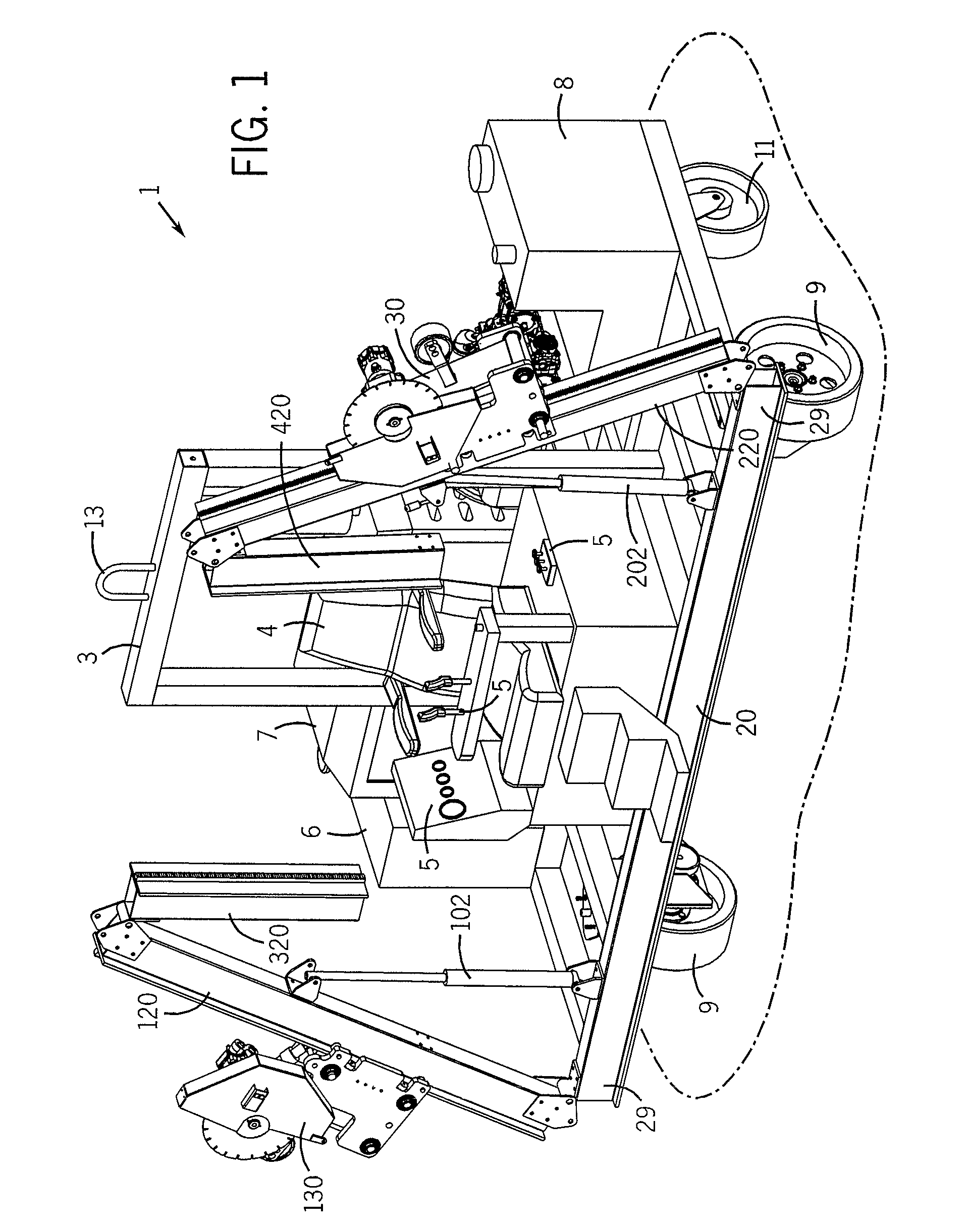
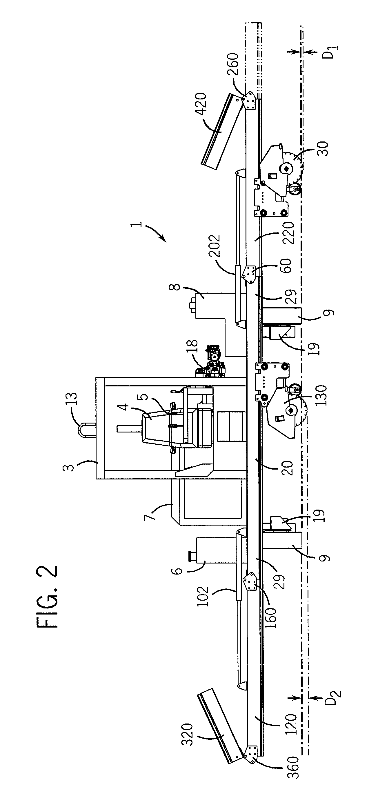
[0022]Referring now to the drawings in detail, wherein like numerals represent like structure and elements throughout, FIG. 1 illustrates a preferred embodiment of the improved concrete cutter of the present invention, generally identified 1. As shown, the improved concrete cutter 1 comprises a generally horizontally-disposed chassis 2, a forward-most portion of the chassis 2 being comprised of a primary boom 20. Extending upwardly from the chassis 2 is an upright frame support member 3, this upright member 3 including a lifting hook 13 that is provided for purposes of hoisting the concrete cutter 1 when such is desired or required, such as when loading the cutter 1 upon a trailer bed for transport.

[0023]Situated forwardly of the upright support member 3 is a seat 4 that is intended to be used by the operator of the cutter 1. Forwardly and to either side of the seat 4 are user controls 5 of conventional manufacture. The controls 5 may include, among other things, wheel drive levers,...


PUM

PropertyMeasurementUnit
diameteraaaaaaaaaa
angleaaaaaaaaaa
cutting depthaaaaaaaaaa

Abstract

An improved concrete cutter has a longitudinally-extending primary boom and one or more saw carriage sub-assemblies that move along the length of the boom. “Wing-like” boom extensions are hingedly secured at each end of the primary boom. The boom extensions can be easily positioned at each end of the primary boom to extend the cutting width of the concrete cutter and without requiring removal of the boom extensions from the concrete cutter. The saw carriage sub-assemblies are independently movable along the boom extensions. Carriage spacing is variably-adjustable along the boom such that each saw carriage can move toward or away from the other saw carriage. Each saw carriage sub-assembly is height-variable and is self-adjusting to contours in the profile of the concrete surface being cut.

Description

[0001]This application claims the benefit and priority of U.S. Provisional Patent Application Ser. No. 60 / 779,749 filed Mar. 7, 2006.FIELD OF THE INVENTION[0002]This invention relates generally to saws and to sawing equipment of the type used for cutting grooves into material such as concrete pavement and the like. More particularly, this invention relates to an improved concrete cutter of the riding type that serves as a vehicle for the operator, the improved concrete cutter having a novel boom and concrete cutting carriage sub-assembly for enhanced cutting capabilities and performance.BACKGROUND OF THE INVENTION[0003]The present inventors are aware of prior art that provides various motor-driven or powered saws for cutting grooves into materials such as concrete pavement and the like. Indeed, this is old art. Grooves are most commonly cut in concrete pavement and related materials by such saws as a means for controlling the cracking of such materials, particularly in areas where w...

Claims


Application Information

Patent Timeline
Patent Type & Authority Patents(United States)
IPC IPC(8): B28D1/04
CPCB28D1/045
Inventor KETTERHAGEN, FREDERICK A.KETTERHAGEN, KEVIN F.MERTES, ANTHONY J.BARGER, GARY L.
Owner SPIDER CUT IP
Why Eureka
Try Eureka