Apparatus and methods for utilizing a downhole deployment valve
What is Al technical title?
Al technical title is built by PatSnap Al team. It summarizes the technical point description of the patent document.
a technology of deployment valve and deployment valve, which is applied in the direction of fluid removal, borehole/well accessories, survey, etc., can solve the problems of creating a dangerous pressure increase or blowout at the surfa
Inactive Publication Date: 2008-11-18
WEATHERFORD TECH HLDG LLC
View PDF88 Cites 77 Cited by
Summary
Abstract
Description
Claims
Application Information
AI Technical Summary
This helps you quickly interpret patents by identifying the three key elements:
Problems solved by technology
Method used
Benefits of technology
Problems solved by technology
Thus, the object may damage the DDV due to the weight and speed of the object upon reaching the DDV, thereby permitting the stored energy of the pressure below the DDV to bypass the DDV and either eject the dropped object from the wellbore or create a dangerous pressure increase or blow out at the surface.
Method used
Image
Click on the blue label to locate the original text in one second.
Reading with bidirectional positioning of images and text.
Examples
Embodiment Construction
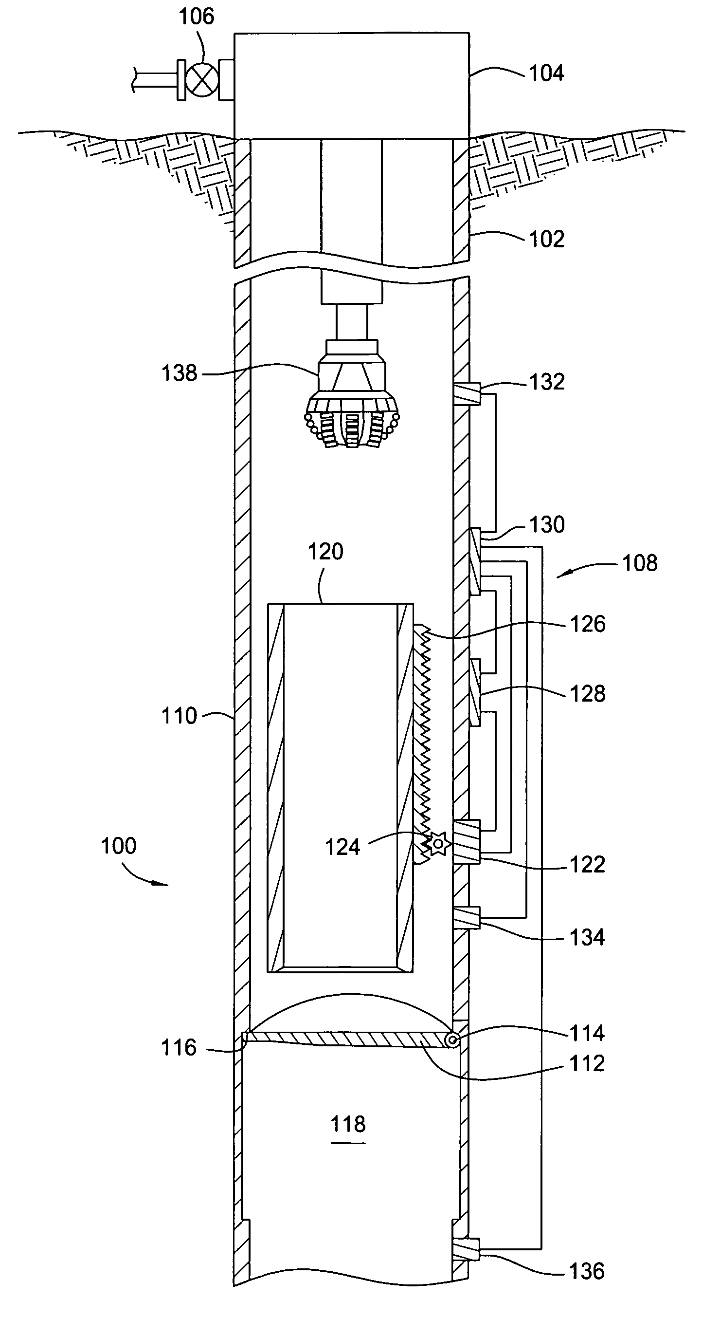
[0030]The invention generally relates to methods and apparatus for utilizing a downhole deployment valve (DDV) in a wellbore. For some of the embodiments shown, the DDV may be any type of valve such as a flapper valve or ball valve. Additionally, any type of actuation mechanism may be used to operate the DDV for some of the embodiments shown.
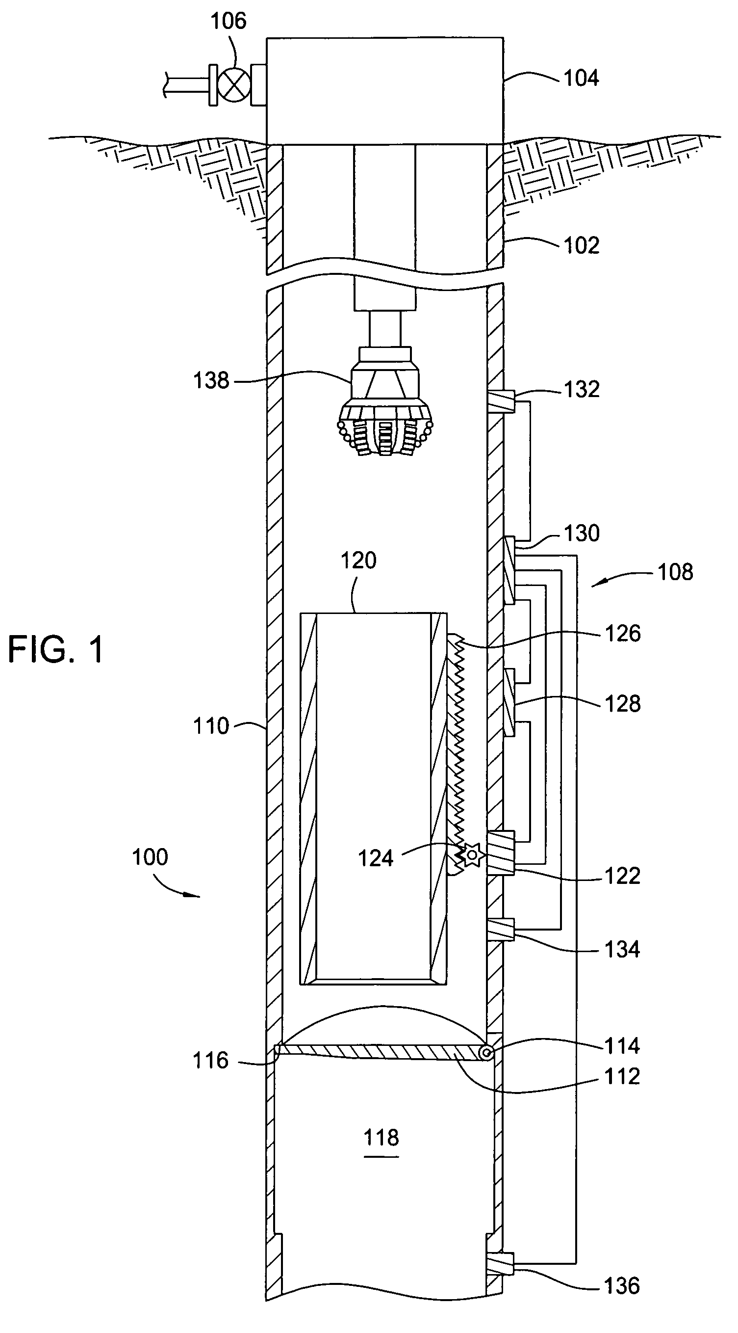
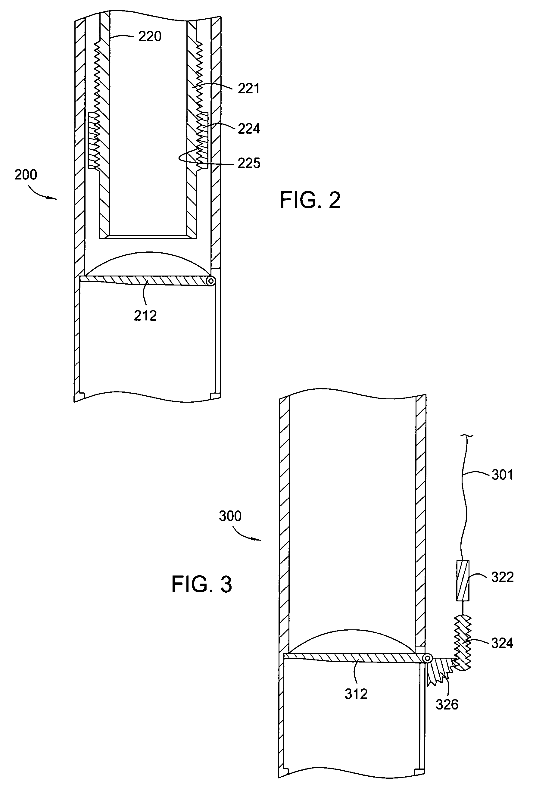
[0031]FIG. 1 illustrates a downhole deployment valve (DDV) 100 within a casing string 102 disposed in a wellbore. The casing string 102 extends from a surface of the wellbore where a wellhead 104 would typically be located along with some type of valve assembly 106 which controls the flow of fluid from the wellbore and is schematically shown. The DDV 100 includes an electrically operated actuation and sensor system 108 self contained downhole, a housing 110, a flapper 112 having a hinge 114 at one end, and a valve seat 116 in an inner diameter of the housing 110 adjacent the flapper 112. Arrangement of the flapper 112 allows it to close in an up...
PUM
Abstract
Methods and apparatus for utilizing a downhole deployment valve (DDV) to isolate a pressure in a portion of a bore are disclosed. The DDV system can include fail safe features such as selectively extendable attenuation members for decreasing a falling object's impact, a normally open back-up valve member for actuation upon failure of a primary valve member, or a locking member to lock a valve member closed and enable disposal of a shock attenuating material on the valve member. Actuation of the DDV system can be electrically operated and can be self contained to operate automatically downhole without requiring control lines to the surface. Additionally, the actuation of the DDV can be based on a pressure supplied to an annulus.
Description
CROSS-REFERENCE TO RELATED APPLICATIONS[0001]This application is a continuation-in-part of U.S. patent application Ser. No. 10 / 270,015, filed Oct. 11, 2002 now U.S. Pat. No. 7,086,481; is a continuation-in-part of U.S. patent application Ser. No. 10 / 288,229, filed Nov. 5, 2002 now U.S. Pat. No. 7,350,590; and is a continuation-in-part of U.S. patent application Ser. No. 10 / 783,982, filed Feb. 20, 2004 now U.S. Pat. No. 7,178,600, which is a continuation in part of U.S. patent application Ser. No. 10 / 677,135, filed Oct. 1, 2003 now U.S. Pat. No. 7,255,173, and U.S. patent application Ser. No. 10 / 676,376, filed Oct. 1, 2003 now U.S. Pat. No. 7,219,729, and which claims benefit of U.S. Provisional Patent Application Ser. No. 60 / 485,816, filed Jul. 9, 2003, all herein incorporated by reference in their entirety.BACKGROUND OF THE INVENTION[0002]1. Field of the Invention[0003]Embodiments of the invention generally relate to methods and apparatus for use in oil and gas wellbores. More part...
Claims
Application Information
Patent Timeline
Application Date:The date an application was filed.
Publication Date:The date a patent or application was officially published.
First Publication Date:The earliest publication date of a patent with the same application number.
Issue Date:Publication date of the patent grant document.
PCT Entry Date:The Entry date of PCT National Phase.
Estimated Expiry Date:The statutory expiry date of a patent right according to the Patent Law, and it is the longest term of protection that the patent right can achieve without the termination of the patent right due to other reasons(Term extension factor has been taken into account ).
Invalid Date:Actual expiry date is based on effective date or publication date of legal transaction data of invalid patent.
Patent Type & Authority Patents(United States)
IPC IPC(8): E21B34/12E21B34/06E21B34/14E21B41/00
CPCE21B34/06E21B41/0021E21B34/00
Inventor NOSKE, JOEBRUNNERT, DAVID J.PAVEL, DAVIDBANSAL, RAMKUMAR K.HAUGEN, DAVIDLUKE, MIKE A.