Blow out preventer transfer platform

a technology of preventing platform and transfer platform, which is applied in the field of offshore drilling operations, can solve the problems of large pieces that are cumbersome, dangerous environment for workers and facilities, and drilling rigs that cannot lift the bop

Active Publication Date: 2008-11-18
SAUDI ARABIAN OIL CO
View PDF32 Cites 31 Cited by
  • Summary
  • Abstract
  • Description
  • Claims
  • Application Information

AI Technical Summary

Problems solved by technology

BOPs can weigh up to 40,000 lbs., and have large pieces that are cumbersome while being moved between various positions.
The drilling rig cannot lift the BOP and continue drilling operations through the same opening in the upper surface of the cantilever.
This creates a dangerous environment for the workers and the facilities.

Method used


Image

  • Blow out preventer transfer platform
  • Blow out preventer transfer platform
  • Blow out preventer transfer platform

Examples


Embodiment Construction

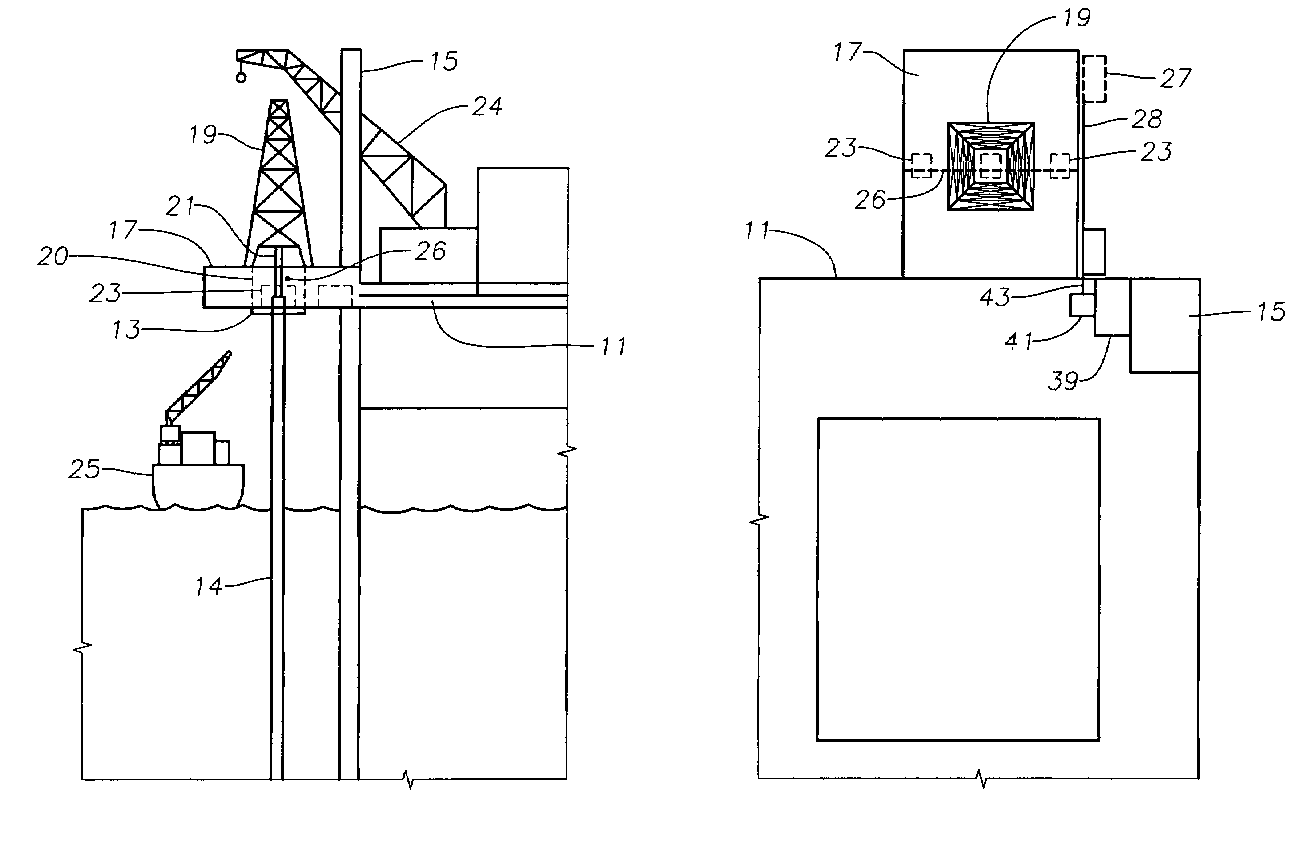
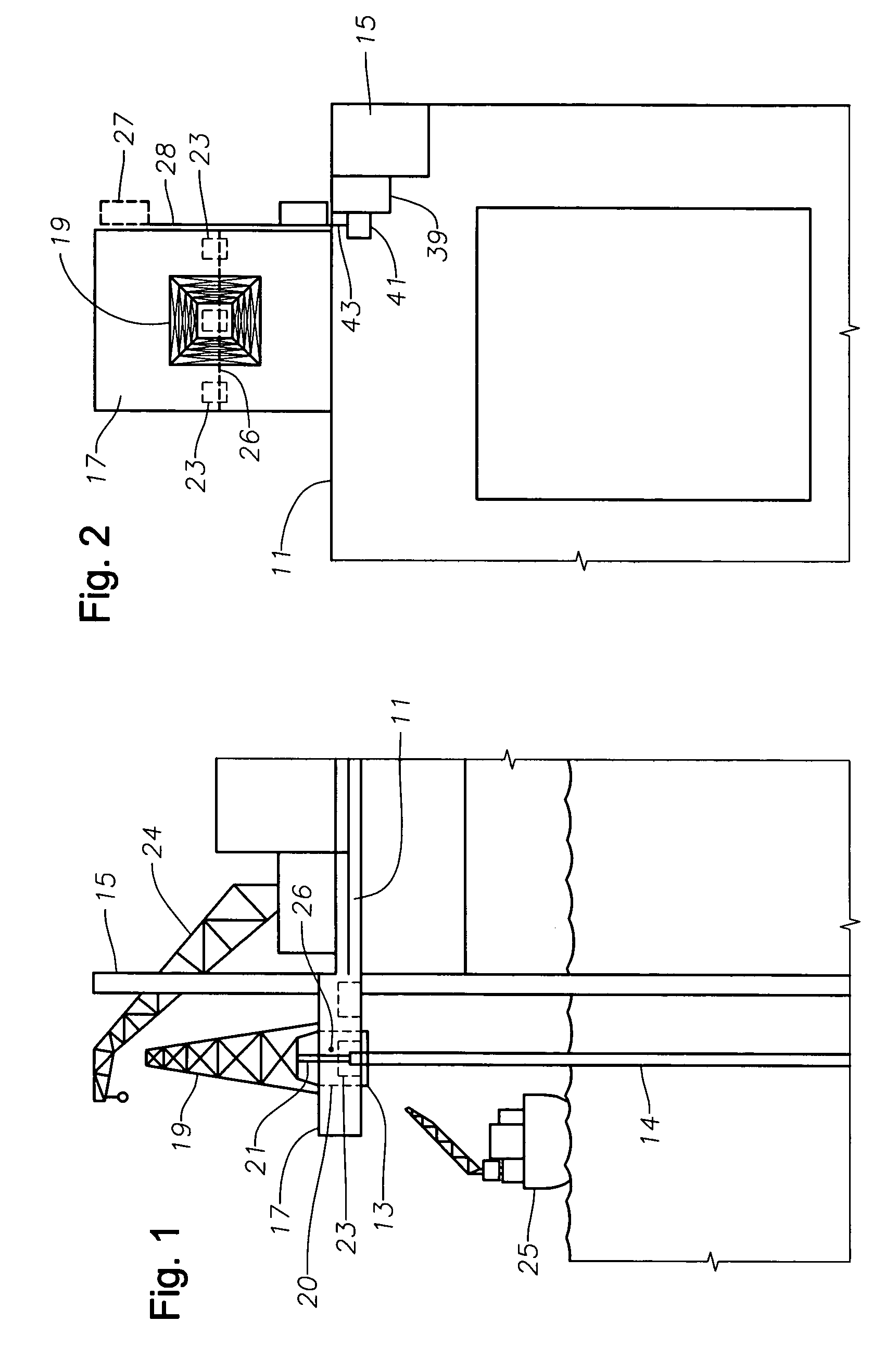
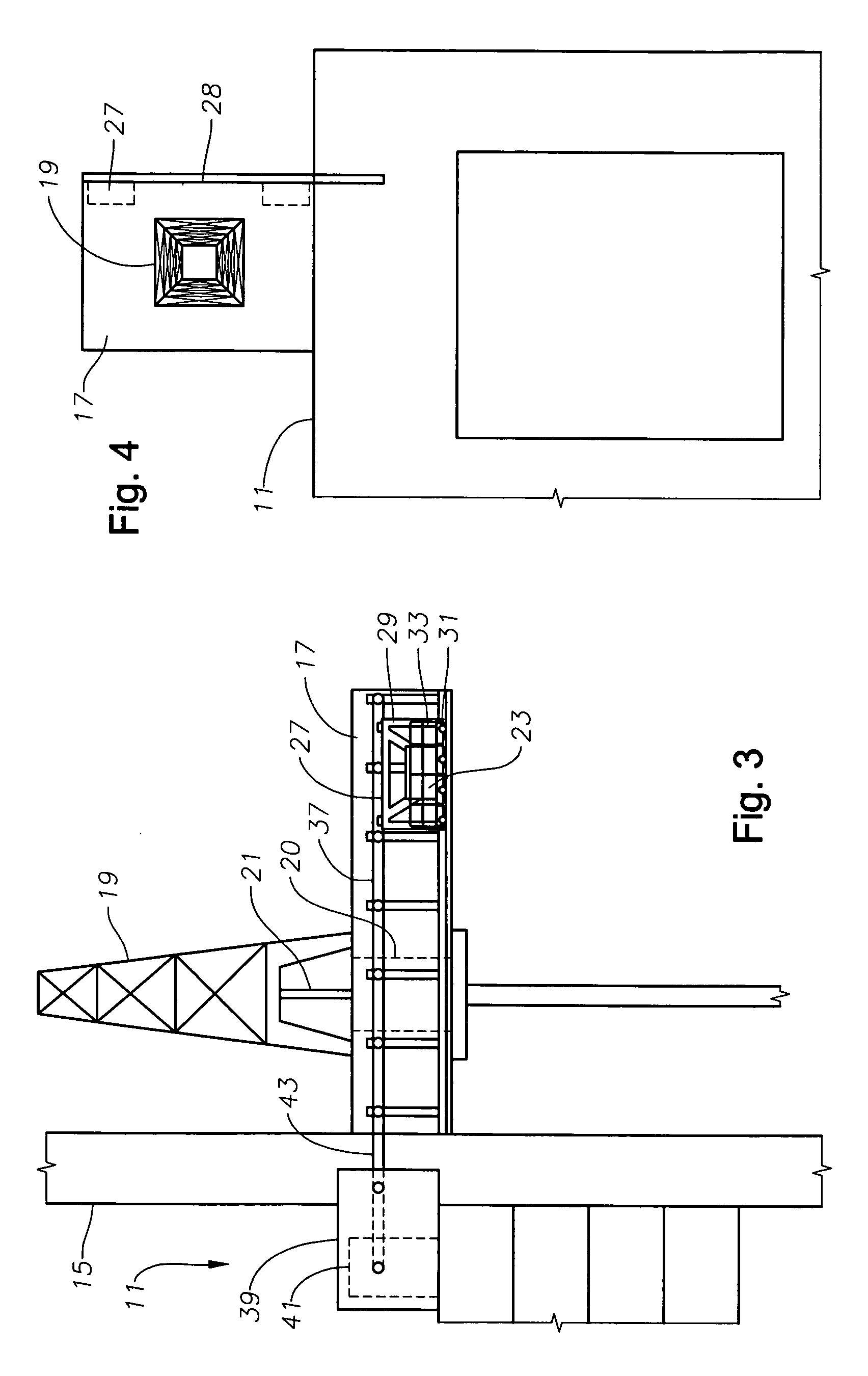
[0019]Referring to FIG. 1, a support platform or offshore drilling facility 11 is located adjacent a working platform 13 formed toward an upper portion of a conductor casing 14 extending from a subsea well. A plurality of legs 15 support facility 11 above the surface of the water. A drilling platform or cantilever 17 extends from a side of facility 11 over the water and working platform 13. A drilling rig 19 is located on cantilever 17, above working platform 13, for conducting drilling operations. Cantilever 17 includes a vertical opening 20 for drilling rig 19 to engage conductor casing 14. A string of drill pipe 21 extends from drilling rig 19, through cantilever 17, and enters conductor casing 14 above working platform 13. A motor or drive unit (not shown), typically located in drilling rig 19, rotates drill pipe 21 during drilling operations. A crane 24 is preferably located on facility 11 for moving equipment and the loading and unloading equipment and supplies. A vessel 25 is...


PUM


Abstract

An offshore well drilling assembly includes a drilling facility or support platform for location at sea. A drilling platform connects to the support platform so the drilling platform is cantilevered from the support platform. The drilling platform extends from the support platform, for positioning over a subsea well. The well drilling assembly includes a staging platform for use in loading and unloading of wellhead equipment. The staging platform is mounted to the drilling platform. The staging platform moves along a side of the drilling platform in directions toward and away from the support platform to a distance over the sea. A method of conveying wellhead equipment uses the staging platform for conveying wellhead equipment between the support platform and a distance over the sea by moving the staging platform along the drilling platform.

Description

RELATED APPLICATIONS[0001]This nonprovisional patent application claims the benefit of co-pending, provisional patent application U.S. Ser. No. 60 / 515,342, filed on Oct. 29, 2003, which is hereby incorporated by reference in its entirety.BACKGROUND OF THE INVENTION[0002]1. Field of the Invention[0003]The present invention relates generally to offshore drilling operations, and more specifically to an apparatus for removing and installing drilling equipment.[0004]2. Background of the Invention[0005]An offshore drilling facility includes a drilling rig for various operations performed while drilling a subsea well. A conductor casing extends from the subsea well to an elevation above the surface of the water, where a working platform is connected to an upper portion of the conductor casing for drilling operators to work. On many facilities, the drilling rig is often supported by a drilling platform or cantilever that extends from a side of the drilling facility, over the water, to a loc...

Claims


Application Information

Patent Timeline
Patent Type & Authority Patents(United States)
IPC IPC(8): E21B29/12E21B7/12B63B21/50B63B35/44E02B17/00E21B15/02E21B19/00E21B33/076
CPCB63B27/02E21B15/02E21B19/002B63B21/502B63B35/4413E02B17/00B63B27/19
Inventor RASHID, OMAR A.RAWLS, ROBERT J.
Owner SAUDI ARABIAN OIL CO
Why Eureka
Try Eureka