Golf ball
a technology of golf ball and ball, applied in the field of golf balls, can solve the problems of loss of distance, increase the distance of travel, and small drag coefficient, and achieve the effect of optimizing the trajectory and advantageously increasing the distance traveled by the ball
Active Publication Date: 2008-11-18
BRIDGESTONE SPORTS
View PDF9 Cites 3 Cited by
- Summary
- Abstract
- Description
- Claims
- Application Information
AI Technical Summary
Benefits of technology
The invention provides a golf ball with optimized trajectory when hit, which has numerous dimples on its surface arranged in different types and sizes. The dimples have a specific shape near the bottom that allows the ball to travel longer distances. The ball has a resilient solid core, a cover made of polyurethane elastomer, and an intermediate layer made of ionomer resin. The cover has a specific thickness and hardness, and the intermediate layer has a specific hardness. The ball has a two-layer construction composed of an inner layer and an outer layer, and the cover has a specific hardness. The invention also provides specific radii of curvature for the dimples and specific angles between the dimple and a circular plane. The total number of dimples ranges from 250 to 370.
Problems solved by technology
Under low-spin conditions, the ball that has been hit will have a small coefficient of drag, which tends to increase its distance of travel.
Yet, when the dimples that have been used in earlier golf balls are used unchanged in these more advanced golf balls, a drop occurs due to insufficient lift in the region of diminished speed after the ball has reached the highest point of its trajectory, resulting in a loss of distance.
Method used
View moreImage
Smart ImageViewing Examples
Examples
examples
[0047]The following Example of the invention and Comparative Example are provided by way of illustration and not by way of limitation.
Login to View More PUM
 Abstract
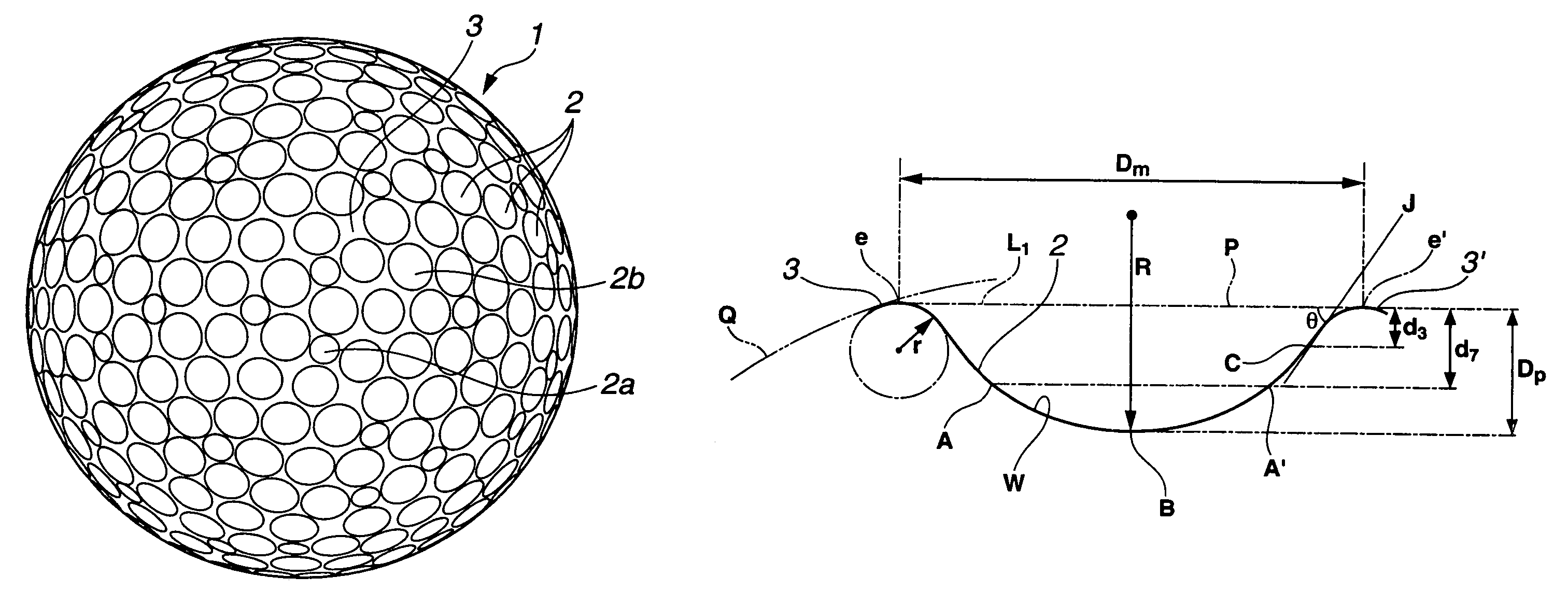
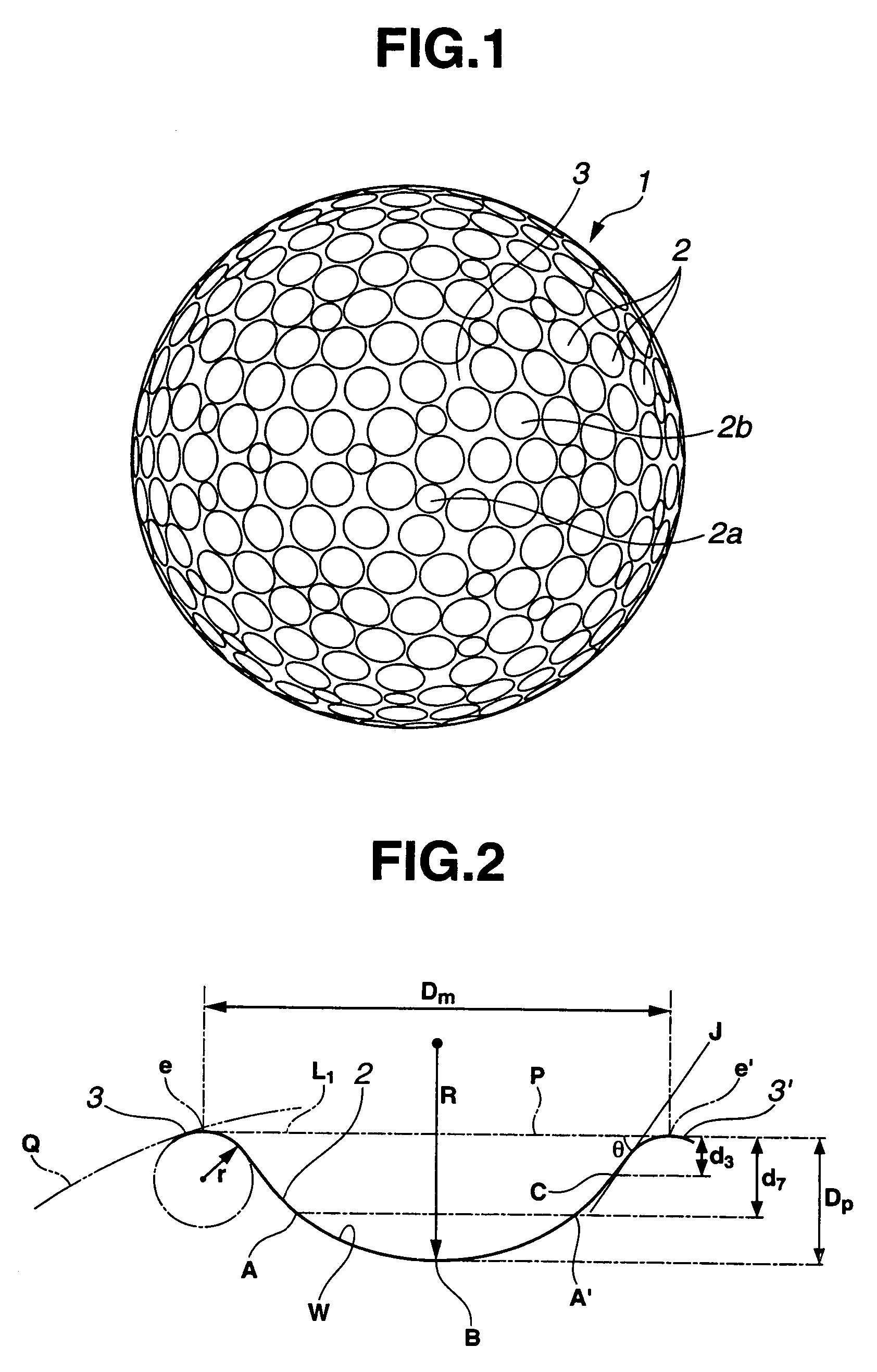
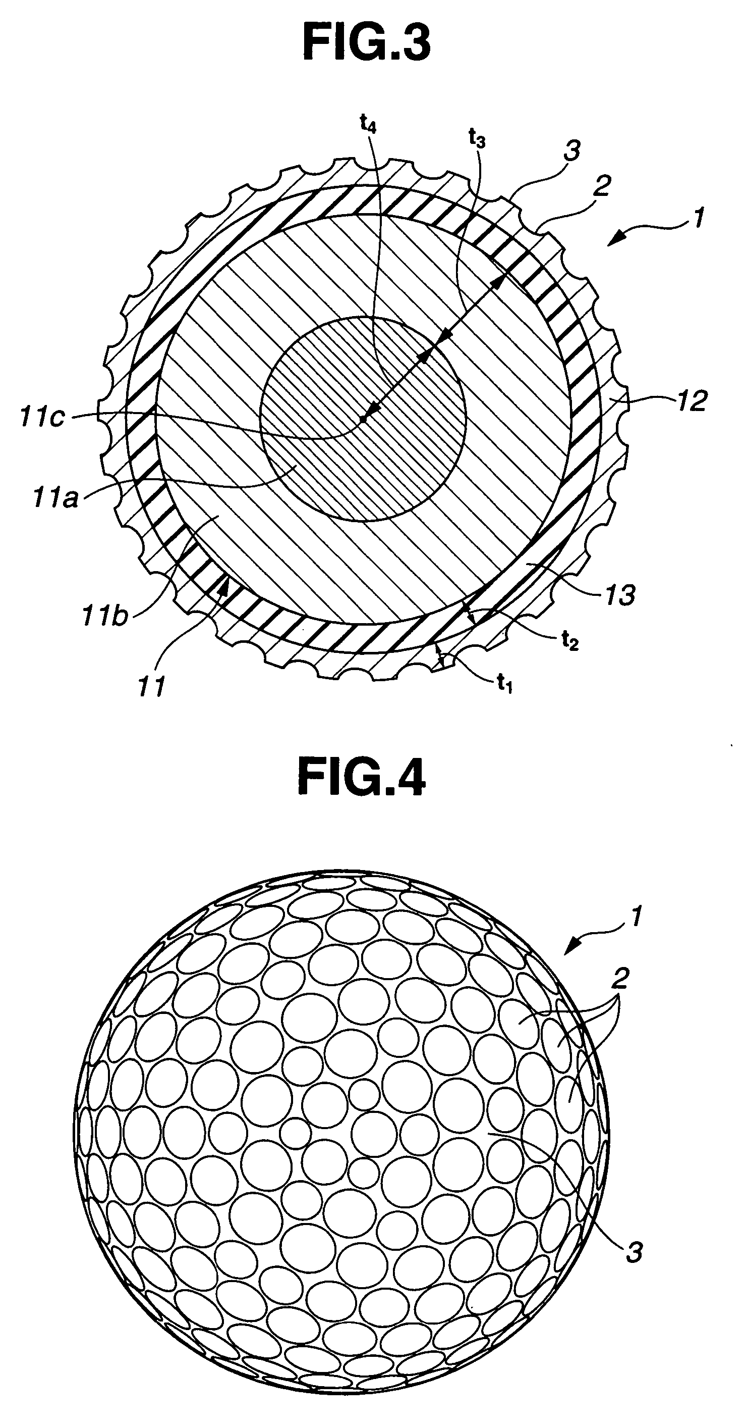
In a golf ball having, on a spherical surface, numerous dimples in a plurality of types of differing diameter, the dimples include smallest size dimples having a diameter of 2.7 mm or less and largest size dimples having a diameter of 4.3 mm or less. At least 50% of the total number of dimples are dimples in which an arc that connects mutually opposing positions on a wall of the dimple at a 70% dimple depth level with a deepest position on the dimple wall has a radius of curvature R of at least 15 mm.
Description
BACKGROUND OF THE INVENTION[0001]The present invention relates to a golf ball having an excellent flight performance.[0002]In the past, to improve both the feel of solid golf balls on impact and their controllability, such balls were optimized for properties such as core and cover hardness under high-trajectory conditions owing to a relatively high spin rate.[0003]It was later found that a golf ball hit at a low spin and a high launch angle will travel a longer distance. Accordingly, greater effort has come to be devoted to increasing the distance of travel in a manner that is in keeping with these findings. With recent advances in golfing equipment such as balls and clubs, designs are being worked out on drivers and other distance clubs that greatly reduce the amount of backspin taken on by a golf ball when it is hit.[0004]Under low-spin conditions, the ball that has been hit will have a small coefficient of drag, which tends to increase its distance of travel. Yet, when the dimple...
Claims
Login to View More Application Information
Patent Timeline
 Patent Type & Authority Patents(United States)
IPC IPC(8): A63B37/12
CPCA63B37/0012A63B37/0018A63B37/002A63B37/0021A63B37/0017A63B37/0019A63B37/0031A63B37/0033A63B37/0043A63B37/0045A63B37/0062A63B37/0064A63B37/008A63B37/00622A63B37/00621A63B37/00215
Inventor KASASHIMA, ATSUKISATO, KATSUNORI
Owner BRIDGESTONE SPORTS
Features
- R&D
- Intellectual Property
- Life Sciences
- Materials
- Tech Scout
- Unparalleled Data Quality
- Higher Quality Content
- 60% Fewer Hallucinations
Learn More Browse by: Latest US Patents, China's latest patents, Technical Efficacy Thesaurus, Application Domain, Technology Topic, Popular Technical Reports.
© 2025 PatSnap. All rights reserved.Legal|Privacy policy|Modern Slavery Act Transparency Statement|Sitemap|About US| Contact US: help@patsnap.com


