
Method for optimized autonomous driving of vehicle

A technology for autonomous driving and vehicles, applied in the direction of vehicle components, other vehicle parameters, vehicle status input parameters, etc., can solve problems affecting the trajectory, and achieve the effect of optimizing the trajectory characteristics and optimizing the trajectory

Pending Publication Date: 2021-03-05
DR ING H C F PORSCHE AG
View PDF7 Cites 0 Cited by
  • Summary
  • Abstract
  • Description
  • Claims
  • Application Information

AI Technical Summary

Problems solved by technology

Targeted influence of trajectories by using the optimizer

Method used


Image

  • Method for optimized autonomous driving of vehicle
  • Method for optimized autonomous driving of vehicle
  • Method for optimized autonomous driving of vehicle

Examples


Embodiment Construction

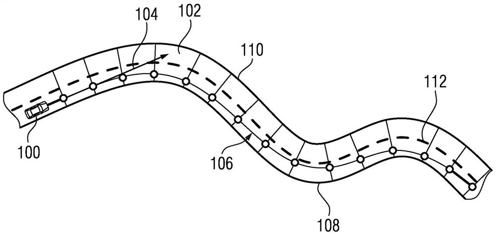
[0035] figure 1 A schematic diagram of a lane 102 for autonomous driving of a vehicle 100 is shown. In the example, vehicle 100 is moving forward in direction of travel 104 . exist figure 1 A trajectory 106 for driving on lane 102 is shown in . Trajectory 106 is one of several possible trajectories by means of which vehicle 100 can move on lane 102 . In this example, a tangent to trajectory 106 gives direction of travel 104 . Trajectory 106 begins directly in front of vehicle 100 .

[0036] Lane 102 is bounded by lane boundary lines. In this example, a right boundary line 108 arranged on the right side of the trajectory 106 relative to the direction of travel 104 and a left boundary line 110 arranged on the left side of the trajectory 106 relative to the direction of travel 104 are shown. In this example, the central isolation strip 112 extends in the middle with respect to these side boundary lines. Lane boundaries can optionally be defined by the side boundaries or by...


PUM


Abstract

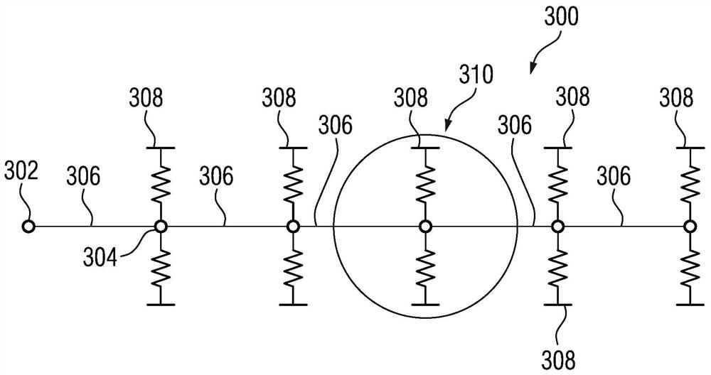
A method and device for optimized autonomous driving are provided. A trajectory (106) for the actuation of a vehicle (100) is determined. A profile of the trajectory (106) is defined by a bending lineof a bending band (300) . The bending line is preferably determined by the finite element method, in particular according to the principle of virtual shifting, and achieves an optimization goal and satisfies a boundary condition. The boundary condition is defined in accordance with a profile of a roadway (102) for the vehicle (100). The optimization goal is defined by a desired driving property of the vehicle (100).

Description

technical field [0001] The present invention relates to methods and devices for autonomous driving of vehicles. Background technique [0002] US 2018 / 0099667 A1 discloses a control method of an autonomous vehicle, wherein the left and right boundary lines of the driving path driven by the vehicle are calculated. Furthermore, an ideal driving route extending within the area of ​​the left and right boundary lines is determined while minimizing the movement distance and minimizing the deviation from the center line. [0003] WO 2017 / 183486 A1 discloses a method for generating a trajectory of an ego vehicle taking into account the acceleration and deceleration of the vehicle so that a gentle driving maneuver is achieved. For this purpose, a trajectory is generated with an inflection point in a curvature change section in which the curvature changes monotonically with respect to the distance traveled by the vehicle. [0004] It would be desirable to provide improved methods and...

Claims


Application Information

Patent Timeline
Patent Type & Authority Applications(China)
IPC IPC(8): B60W30/10B60W40/107B60W40/109B60W30/18B60W40/09B60W40/12B60W40/072
CPCB60W30/10B60W40/107B60W40/109B60W30/18B60W40/09B60W40/12B60W40/072B60W2520/105B60W2520/125B60W2520/10B60W2510/0676B60W2530/20G01C21/3407B60W60/0023B60W2530/209B60W60/0011
Inventor G·塔迪-塔奇F·施特雷克尔M·格拉茨
Owner DR ING H C F PORSCHE AG
Learn More