Antenna device and radar apparatus including the same
a technology of antenna device and radar, which is applied in the direction of antennas, instruments, electrical devices, etc., can solve the problems of increasing the size of the radar apparatus, and achieve the effects of reducing the number of components of the antenna device, excellent durability, and easy manufacturing
- Summary
- Abstract
- Description
- Claims
- Application Information
AI Technical Summary
Benefits of technology
Problems solved by technology
Method used
Image
Examples
first embodiment
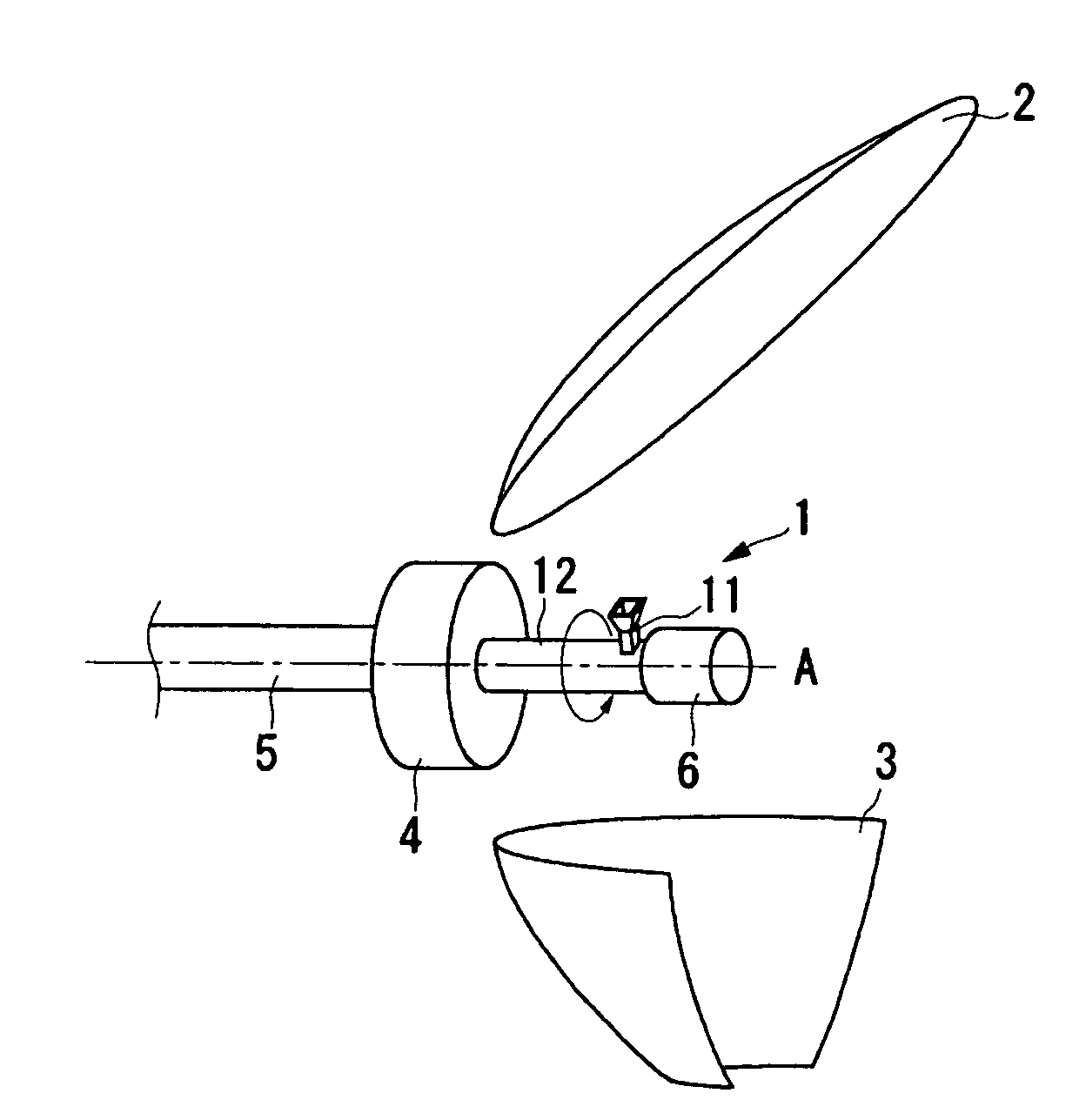
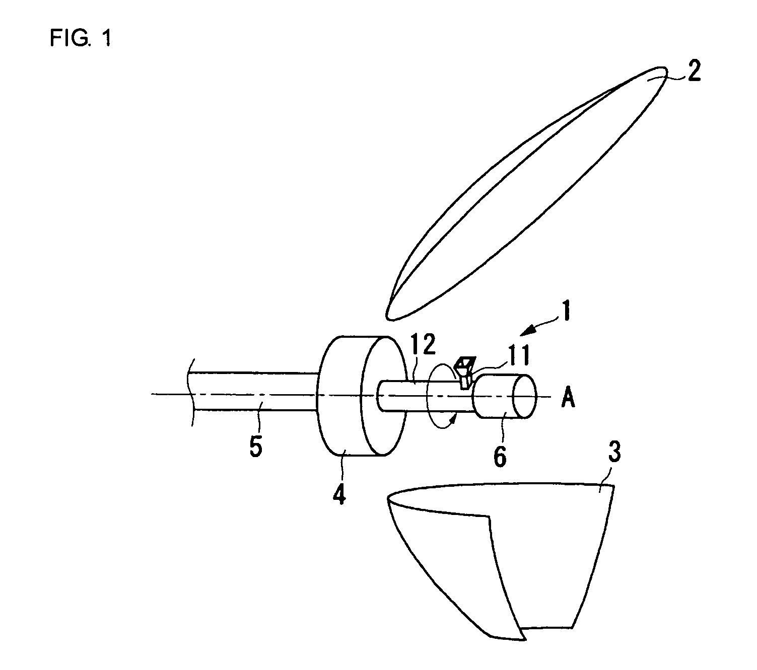
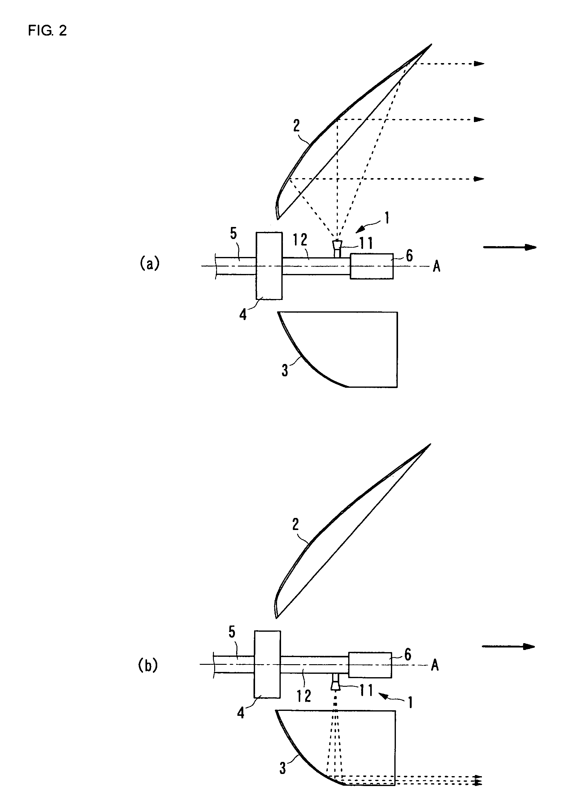
[0052]An antenna device according to the present invention will now be described with reference to FIGS. 1 to 6(d).
[0053]FIG. 1 is an external view of the antenna device according to this embodiment.
[0054]Moreover, FIGS. 2(a) and 2(b) are side views of the antenna device according to this embodiment illustrating a state where a primary radiator 1 is directed to a reflector 2 and a state where the primary radiator 1 is directed to a reflector 3, respectively. Arrows with dotted lines in the drawings indicate directions along which millimeter-wave signals are radiated and directions along which transmission beams composed of the millimeter-wave signals are transmitted, and arrows with thick solid lines indicate the direction in which the front of the antenna device faces (front direction)
[0055]As shown in FIGS. 1, 2(a) and 2(b), the antenna device includes the primary radiator 1, the first reflector 2, the second reflector 3, a rotary joint 4, a waveguide 5, and a motor 6.
[0056]The pr...
second embodiment
[0079]Next, an antenna device will be described with reference to FIGS. 7(a) and 7(b).
[0080]FIGS. 7(a) and 7(b) are side views illustrating schematic structures of the antenna device according to this embodiment. Arrows with dotted lines in the drawings indicate directions along which millimeter-wave signals are radiated and directions along which transmission beams composed of the millimeter-wave signals are transmitted, and arrows with thick solid lines indicate the front direction.
[0081]As shown in FIGS. 7(a) and 7(b), the antenna device according to this embodiment includes a first reflector 2 and a third reflector 7 having the same shape disposed above and below a primary radiator 1, respectively, so as to be disposed symmetrically with respect to a focal point that exists in the primary radiator 1. Structures other than this are the same as those in the first embodiment. With this, the reflecting surface of the first reflector 2 is directed in the front direction of the anten...
third embodiment
[0084]Next, an antenna device will be described with reference to FIGS. 8(a) and 8(b).
[0085]FIGS. 8(a) and 8(b) are side views illustrating schematic structures of the antenna device according to this embodiment. Arrows with dotted lines in the drawings indicate directions along which millimeter-wave signals are radiated and directions along which transmission beams composed of the millimeter-wave signals are transmitted, and arrows with thick solid lines indicate the front direction.
[0086]The antenna device shown in FIGS. 8(a) and 8(b) includes a first reflector 2 disposed above a primary radiator 1, and a fourth reflector 8 disposed below the primary radiator 1 so as to be axisymmetric to the first reflector 2 with respect to a rotation axis A of the primary radiator 1. Beams formed by reflection of the first reflector 2 travel obliquely downward in the front direction, and beams formed by reflection of the fourth reflector 8 travel obliquely upward in the front direction. Struct...
PUM
 Abstract
Description
Claims
Application Information
 - R&D
- Intellectual Property
- Life Sciences
- Materials
- Tech Scout
- Unparalleled Data Quality
- Higher Quality Content
- 60% Fewer Hallucinations
Browse by: Latest US Patents, China's latest patents, Technical Efficacy Thesaurus, Application Domain, Technology Topic, Popular Technical Reports.
© 2025 PatSnap. All rights reserved.Legal|Privacy policy|Modern Slavery Act Transparency Statement|Sitemap|About US| Contact US: help@patsnap.com


