Image generating apparatus

a technology of generating apparatus and holding member, which is applied in the direction of power drive mechanism, instruments, printing, etc., can solve the problems of reduced thickness (screw margin) of the upper chassis to which the screw is fastened, material amount, and difficulty in strong mounting of the head spring on the upper chassis, so as to reduce the thickness of the heat radiation member and the effect of strong mounting of the holding member

Inactive Publication Date: 2008-11-18
FUNAI ELECTRIC CO LTD
View PDF7 Cites 4 Cited by
  • Summary
  • Abstract
  • Description
  • Claims
  • Application Information

AI Technical Summary

Benefits of technology

[0018]The present invention has been proposed in order to solve the aforementioned problems, and an object of the present invention is to provide an image generating apparatus allowing reduction of the thickness of a heat radiation member and allowing strong mounting of a holding member also when a print head is arranged on the forward end of a screw member.

Problems solved by technology

In the facsimile disclosed in the aforementioned Japanese Patent Laying-Open No. 7-111558, however, the thickness (screw margin) of the upper chassis to which the screw is fastened is so reduced that it is difficult to strongly mount the head spring on the upper chassis if the upper chassis is thinned in order to reduce the amount of the material for the upper chassis provided with the head spring as well as the cost, similarly to the conventional thermal transfer printer shown in FIG. 16.
In the facsimile machine disclosed in the aforementioned Japanese Patent Laying-Open No. 2000-58151, however, it is difficult to arrange a member such as a precision machine on the forward end of the screw due to the portion, to which the screw is fastened, formed to protrude toward the forward end of the screw.

Method used


Image

  • Image generating apparatus
  • Image generating apparatus
  • Image generating apparatus

Examples


Embodiment Construction

[0052]An embodiment of the present invention is now described with reference to the drawings.

[0053]First, the structure of a thermal transfer printer according to this embodiment is described with reference to FIGS. 1 to 12. This embodiment of the present invention is applied to the thermal transfer printer, which is an exemplary image generating apparatus.

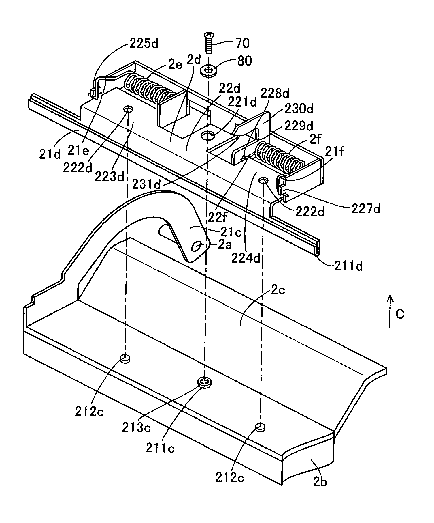
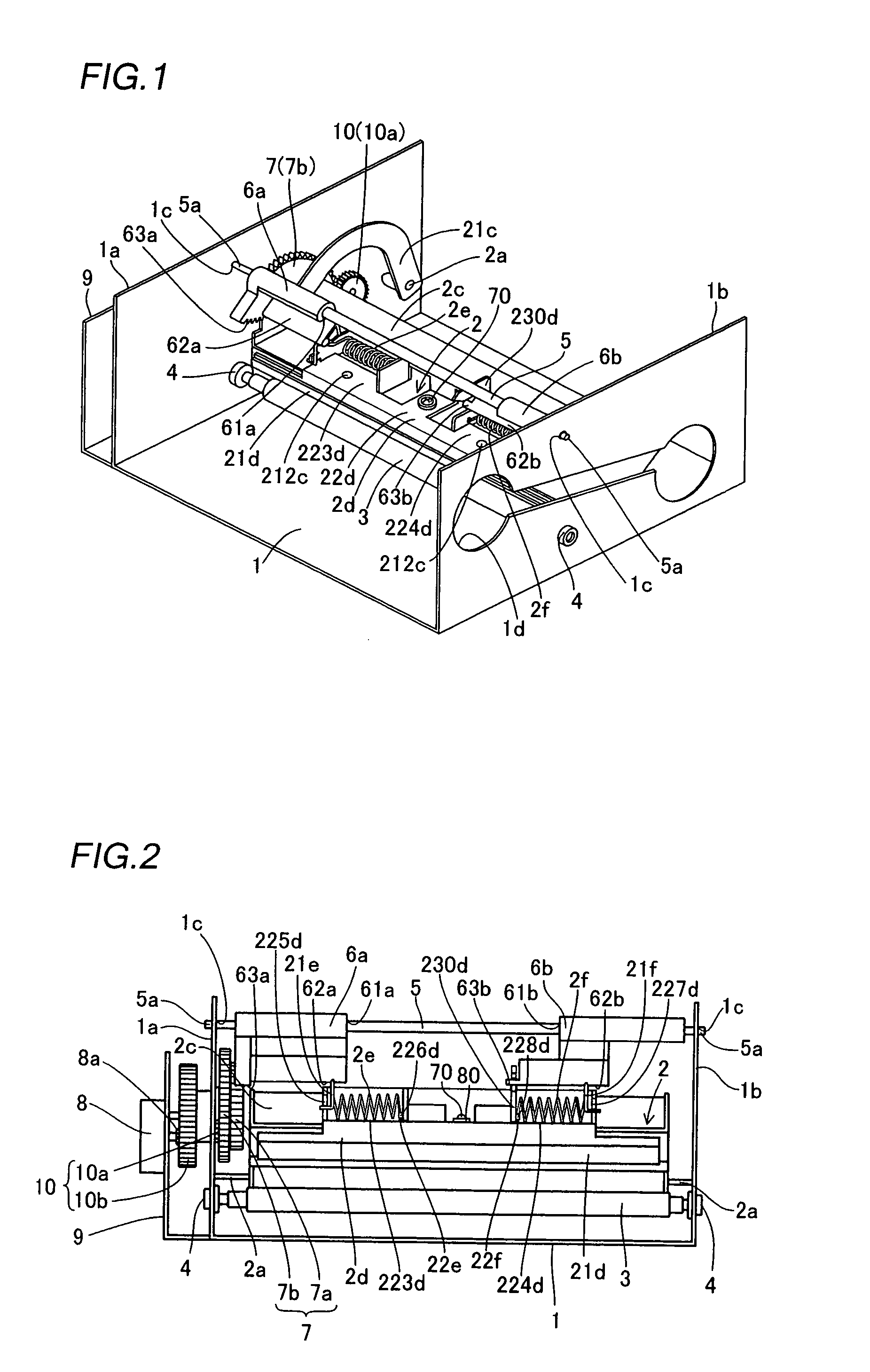
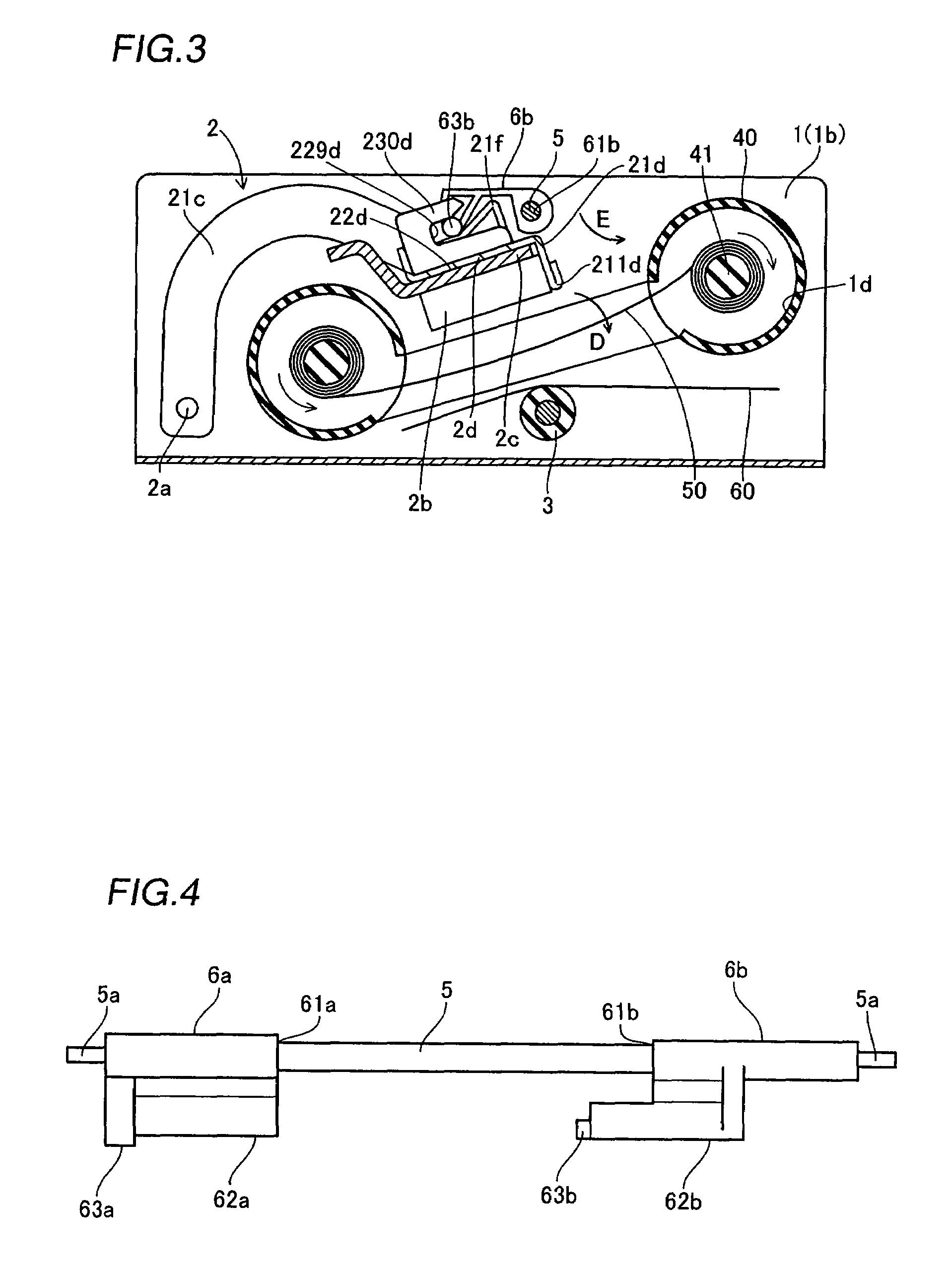
[0054]The thermal transfer printer according to this embodiment comprises a metal chassis 1, a print head 2 for printing, a platen roller 3, two platen roller bearings 4, a metal support rod 5, head portion pressing members 6a and 6b for pressing the print head 2, a resin drive gear 7, a motor 8 (see FIG. 2), a motor bracket 9 and an intermediate gear 10, as shown in FIGS. 1 and 2.

[0055]The chassis 1 has first and second side surfaces 1a and 1b opposed to each other. The first and second side surfaces 1a and 1b of the chassis 1 are provided with support holes 1c for rotatably supporting the support rod 5 respectively. An ink sheet...


PUM


Abstract

An image generating apparatus allowing reduction of the thickness of a heat radiation member and allowing strong mounting of a holding member also when a print head is arranged on the forward end of a screw member is obtained. This image generating apparatus comprises a print head, a heat radiation member, arranged on the upper surface of the print head, including a mounting portion protruding toward the head of a screw member and having a threaded hole meshing with the screw member and a holding member, mounted on the upper surface of the heat radiation member with the screw member, having a mounting portion receiving hole capable of receiving the mounting portion of the heat radiation member and holding a prescribed member.

Description

BACKGROUND OF THE INVENTION[0001]1. Field of the Invention[0002]The present invention relates to an image generating apparatus, and more particularly, it relates to an image generating apparatus comprising a print head.[0003]2. Description of the Background Art[0004]A thermal transfer printer is known as an image generating apparatus comprising a print head. The structure of a print head 100 employed for such a conventional thermal transfer printer is described with reference to FIG. 16.[0005]As shown in FIG. 16, the exemplary conventional print head 100 has a head portion 110 for printing pictures (characters), a rotary arm 120 rotatably supporting the head portion 110 and an ink sheet guide member 130 for guiding an ink sheet 150.[0006]The head portion 110 generates heat, thereby thermally transferring ink from the ink sheet 150 passing through the space between the head portion 110 and a platen roller 140 to a paper 160. The rotary arm 120 includes a heat sink 121, provided on th...

Claims


Application Information

Patent Timeline
Patent Type & Authority Patents(United States)
IPC IPC(8): B41J2/32B41J2/335
CPCB41J2/32B41J2/335B41J2202/31
Inventor NAKATANI, MASAKI
Owner FUNAI ELECTRIC CO LTD
Why Eureka
Try Eureka