
Metal oxide varistor with a heat protection

a technology varistors, which is applied in the direction of varistor cores, emergency protective devices, emergency protective circuit arrangements, etc., can solve the problems of varistors emitted smoke and fumes, varistors may overheat in failure, and the impedance of metal oxide varistors drops to the point where they present a significant load

Inactive Publication Date: 2008-11-18
THINKING ELECTRONICS INDAL
View PDF2 Cites 20 Cited by
  • Summary
  • Abstract
  • Description
  • Claims
  • Application Information

AI Technical Summary

Benefits of technology

"The present invention provides a metal oxide varistor with a heat protection structure that automatically goes to open circuit in conditions of overheating due to sustained over-voltages. The fuse is connected to the body of the varistor and is mounted in a slot on the insulation bracket. The fuse is wrapped with heat shrinkable material or surrounded with electrical insulated glue to retain its space for movement and to act as a safety thermal barrier. The technical effect of the invention is to provide a reliable and efficient protection against damage due to sustained over-voltages."

Problems solved by technology

While the metal oxide varistors have a long life and have the ability to repeatedly clamp high transient voltage spikes to a safe level, the metal oxide varistors do eventually fail and ultimately, even if a catastrophic failure does not occur, the impedance of metal oxide varistors decreases to the point where they present a significant load, and eventually overheat and fail emitting smoke and fumes.
While these thermal protective fuses heretofore used to protect electrical circuits from varistor failure have been somewhat effective, varistors may overheat in failure if localized overheating occurs at a portion of the varistor body remote from the fuse, the varistor and surrounding areas may be substantially destroyed before the temperature at the location of the fuse increases sufficiently to cause the fuse open.
While these varistors appear to be reasonably effective, it still suffers from some drawbacks.
It is doubtful whether a reliable insulation gap can be formed after fusing with relying on properties such as outgassing in an epoxy.

Method used


Image

  • Metal oxide varistor with a heat protection
  • Metal oxide varistor with a heat protection
  • Metal oxide varistor with a heat protection

Examples


Embodiment Construction

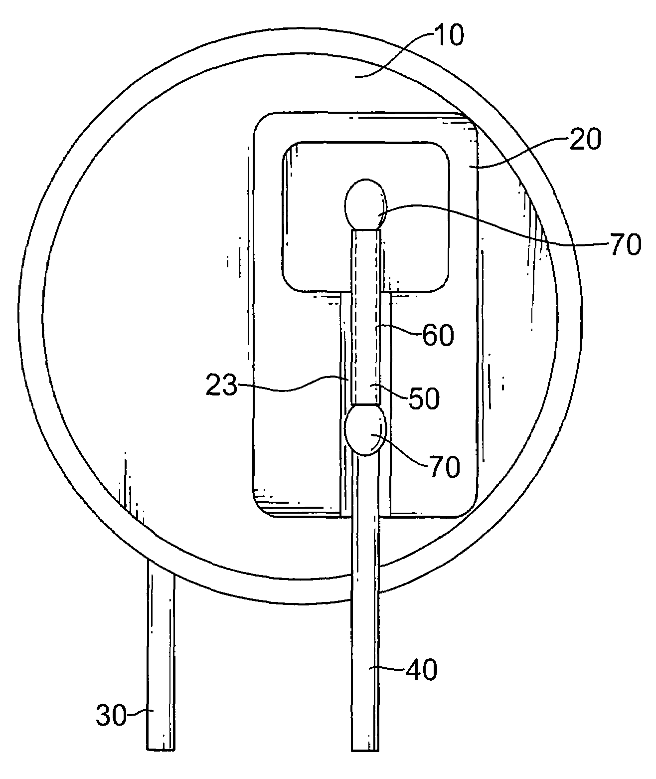
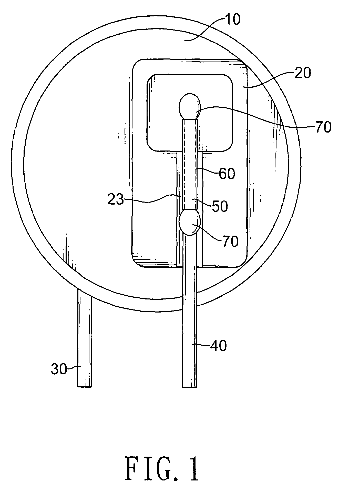
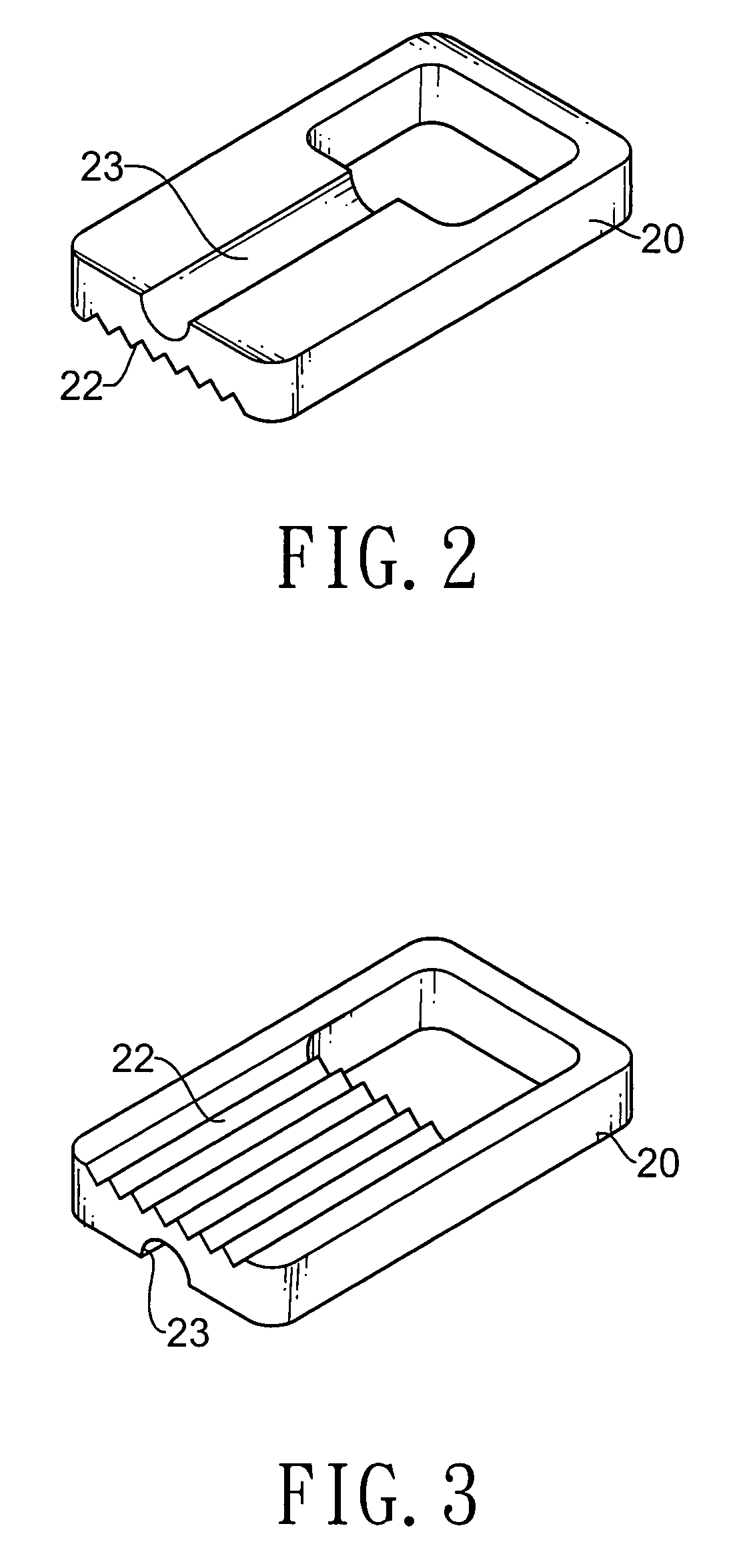
[0021]With reference to FIGS. 1, 4, 5, 7, 9 and 10, a metal oxide varistor with a heat protection in accordance with the present invention comprises a body (10, 10′), an insulation bracket (20, 20′), a first terminal (30, 30′), a second terminal (40, 40′), a third terminal (401), a fuse (50, 50′), a heat-shrinkable element (60, 60′), multiple solder joints (70, 70′) and a glue (80, 80′).

[0022]The body (10, 10′) has a first side and a second side.

[0023]With further reference to FIGS. 2, 3 and 8, the insulation bracket (20, 20′) is made of ceramics that is a well heat conductor, is insulated from electricity, is attached securely on the first side of the body (10, 10′) and has an inner side, an outer side, a longitudinal slot (23, 23′). The inner side of the insulation bracket (20, 20′) faces the body (10, 10′). The insulation bracket (20) has multiple teeth (22), or the insulation bracket (20′) has a notch (21′) and multiple receiving slots (22′). The longitudinal slot (23, 23′) is f...


PUM


Abstract

A metal oxide varistor integrally formed with a heat protection structure that will automatically go to open circuit in conditions of overheating due to sustained over-voltages. The metal oxide varistor integrally formed with a heat protection structure has a body, an insulation bracket, a number of terminals and a fuse. The insulation bracket is deposited on the body and has a number of slots. The fuse connects to the body and one of the terminals. The fuse is mounted one of the slots of the insulation bracket. The fuse reacts to the overheating timely and the melting fuse spreads quickly with the assistance of capillary action evolved by the slots of the insulation bracket to speed up the action to go to open circuit in against damage due to sustained over-voltages.

Description

BACKGROUND OF THE INVENTION[0001]1. Field of the Invention[0002]The present invention is generally directed to a metal oxide varistor having a heat protection, especially to a metal oxide varistor integrally formed with an automatic switching-off structure that automatically goes to open circuit in conditions of overheating due to sustained over-voltages.[0003]2. Description of the Prior Arts[0004]Metal oxide varistors are widely used in circuits as voltage protection elements and inrush-current-absorbing elements. The metal oxide varistors have the capability of clamping high transient voltages appearing on unconditioned power lines to a low level for protecting electrical equipment or devices connected to the line. While the metal oxide varistors have a long life and have the ability to repeatedly clamp high transient voltage spikes to a safe level, the metal oxide varistors do eventually fail and ultimately, even if a catastrophic failure does not occur, the impedance of metal ox...

Claims


Application Information

Patent Timeline
Patent Type & Authority Patents(United States)
IPC IPC(8): H02H1/00H01C7/10H01C7/13
CPCH01C1/08H01C7/108H01H37/761H01H2085/0008
Inventor HO, CHANG-WEI
Owner THINKING ELECTRONICS INDAL
Learn More